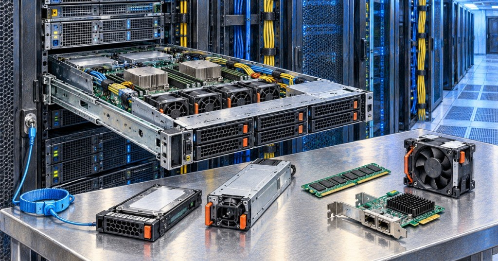
Server FRU replacement is the controlled removal and installation of field-replaceable hardware while preserving service availability, hardware compatibility, safety, and configuration integrity. A technician must know whether a component is truly hot-swappable, whether the host must be powered down, which slot or bay is authorized, what ESD controls apply, and how to prove that the replacement restored the intended function.
This lesson follows OSDCTC.009: Server Decommissioning and Media Sanitization. Decommissioning removes equipment from service permanently; FRU replacement keeps the server in service by replacing only the failed or changed component and then validating the resulting hardware state.
Cloud Ninjas demonstrates server memory layout and DIMM installation on a Dell PowerEdge R650.
Elementary Overview
A field-replaceable unit, or FRU, is a server part designed to be replaced in the field rather than repairing the entire server at a factory. Examples include drives, power supplies, fans, memory modules, and network adapters. Some FRUs can be changed while the server is running; others require the machine to be shut down and electrically safe before the chassis is opened.
Learning Objectives
- Distinguish hot-swap, hot-plug, warm-swap, and cold-service replacement conditions.
- Verify the exact server, component, bay, slot, part number, and maintenance authorization before removal.
- Apply ESD and power-safety controls during internal hardware service.
- Replace common FRUs including drives, PSUs, fans, DIMMs, and NICs without disturbing unrelated hardware.
- Preserve cabling, airflow, blanks, slot population rules, RAID state, and redundant power paths.
- Use BMC or management-controller data to verify hardware detection and health after replacement.
- Document serial numbers, asset information, firmware state, test results, and ticket closeout evidence.
Hot-Swap Does Not Mean Every Part Is Safe to Pull Live
Hot-swap capability is specific to the server model, component, bay, backplane, redundancy state, and operating procedure. Dell’s PowerEdge R650 service manual, for example, permits one PSU to be removed from a powered redundant system only while another PSU remains available. A drive marked hot-swap still depends on the backplane, storage controller, RAID or filesystem state, and the correct physical bay being identified first.
Cloud Ninjas demonstrates hot-swap PSU replacement on a Dell PowerEdge R650.
A data-center discussion illustrates why technicians should verify the actual backplane and hardware design instead of assuming that every front-access drive carrier is truly hot-swappable.
Identify the Exact FRU Before Touching Hardware
Before removal, reconcile the ticket with the physical server. Confirm rack, U position, hostname or asset ID, chassis serial or service tag, component type, physical location, failed-component indicator, BMC inventory, and replacement-part number. If the ticket says “replace disk 2,” do not rely on human-readable numbering alone; storage software, RAID controllers, and front-bay labels can use different numbering schemes.
Use identify LEDs or vendor-supported locate functions where available. Compare the failed component’s serial number and slot against the BMC or storage-controller view from OSDCTC.006: BMC and Out-of-Band Server Management. The final physical check should occur immediately before the latch is released.
Lenovo service training shows removal of a hot-swap drive from a ThinkSystem SR650 V3.
ESD and Electrical Safety
Internal server components such as DIMMs, PCIe adapters, system boards, processors, and risers are electrostatic-discharge sensitive. Use the site’s approved ESD program, including grounded work surface or wrist strap where required, antistatic packaging, edge handling, and protection of exposed contacts. Do not treat an ESD strap as an electrical isolation device; electrical safety and ESD protection solve different hazards.
For cold-service work, follow the vendor’s shutdown and de-energization procedure. HPE’s ProLiant service guidance specifically notes that the front power button does not remove all system power and instructs technicians to disconnect the power cords before internal DIMM service. Facility LOTO requirements apply whenever the task or site procedure requires hazardous-energy isolation beyond normal server maintenance.
Drive Replacement
Before removing a drive, verify the correct slot, fault state, array state, rebuild policy, and replacement compatibility. A failed drive in a redundant array may be replaceable online, but pulling a second healthy member from a degraded RAID set can turn a recoverable fault into data loss. After insertion, verify that the new drive is detected and that any expected rebuild, copyback, resilver, or spare transition begins normally.
Record the old and new drive serial numbers and capacities. Do not close the task merely because the latch clicks into place. Confirm controller status, drive health, link speed where exposed, array state, rebuild percentage, and any new BMC or storage alarms. This connects directly to the validation discipline in OSDCTC.005: Server Hardware Troubleshooting.
Power-Supply Replacement
On a dual-PSU server, confirm that the surviving PSU and its upstream feed are healthy before removing the failed unit. Verify that A/B power design remains intact and that both feeds are not accidentally sourced from the same rack PDU or branch circuit. Review the rack-power checks from OSDCTC.002: Rack Power Distribution before working on redundant power.
Match PSU wattage, input type, connector type, efficiency class, and vendor compatibility. Some platforms synchronize PSU firmware after replacement, but technicians should still verify model, firmware, input voltage, output state, redundancy mode, load sharing, and alarm clearance after installation.
Fan Replacement
Cooling fans may appear simple, but fan zoning, airflow direction, high-performance fan classes, and system firmware policy matter. Confirm whether the fan is hot-serviceable on the exact platform. If the chassis must be opened or powered down, follow the service manual instead of copying the procedure from another server family.
Dell Enterprise Support demonstrates fan removal and installation on a PowerEdge R650.
After replacement, verify fan RPM or health state in the BMC, confirm that the failed-fan alarm clears, inspect neighboring fan status, and confirm that the system leaves any emergency high-fan-speed mode. Reinstall air shrouds, baffles, blanks, and covers exactly as designed because missing airflow parts can create recirculation or local hot spots even when all fans are spinning.
DIMM Replacement
DIMMs are normally cold-service components. Verify the failed slot, memory population rules, memory type, capacity, rank, speed, and vendor-supported configuration before removal. HPE and Lenovo service documentation both emphasize slot-specific population rules and antistatic handling. A physically compatible DIMM can still produce a degraded or unsupported memory configuration if installed in the wrong channel or mixed incorrectly.
Lenovo service training demonstrates memory-module installation on a ThinkSystem SR650 V3.
After power-up, verify total memory, slot inventory, channel state, ECC or training errors, POST messages, and BMC hardware logs. If the system reports less memory than expected, do not immediately assume the replacement DIMM is defective; inspect seating, population order, compatibility, and whether a memory-training event produced a disabled channel.
NIC and PCIe Adapter Replacement
Replacing a NIC or other PCIe adapter can change more than hardware inventory. Port numbering, MAC addresses, firmware, PCIe slot width, NUMA locality, operating-system interface names, switch configuration, VLANs, bonding or teaming, and application binding may all matter. Capture the original interface identity and cabling before removal.
Cloud Ninjas demonstrates PCIe and OCP network-adapter installation on a Dell PowerEdge R650.
After replacement, validate link state, expected speed and duplex, transceiver or DAC detection, MAC address, VLAN or bond membership, BMC inventory, and switch-port state. The server-side and network-side validation steps from OSDCTC.008: Server Network Configuration and Validation should be repeated whenever a NIC replacement changes the physical interface.
Never Disturb Unrelated Cables or Components
A disciplined FRU replacement changes the smallest possible failure domain. Photograph or document cable positions if site policy allows, label temporary disconnects, preserve fiber bend radius, keep A/B power paths separated, and do not move neighboring drives, DIMMs, risers, or network cables unless the service procedure explicitly requires it. Review the physical-discipline rules from OSDCTC.003: Structured Cabling and Patch Panels.
Post-Replacement Verification
The replacement is not complete when the new hardware is physically installed. Verify that the server detects the component with the correct identity and health state, that the original fault clears, that no new fault appears, and that the service affected by the component is functional. Compare pre-change and post-change BMC inventory, event logs, sensor state, firmware versions, and component serial numbers.
Lenovo demonstrates device-inventory visibility in XClarity One, illustrating the kind of post-change inventory confirmation expected after hardware service.
- Drive: detected, correct capacity, healthy state, expected rebuild/resilver behavior.
- PSU: detected, input present, output healthy, redundancy restored, no power mismatch alarm.
- Fan: detected, expected RPM or health, thermal alarms clear, normal fan policy restored.
- DIMM: correct total memory, correct slot, no ECC/training fault, expected channel population.
- NIC: correct model, firmware, MAC, link speed, switch visibility, VLAN/bond configuration.
Ticket and Change Documentation
A strong closeout record states what failed, what evidence identified the component, which FRU was removed, which FRU was installed, the old and new serial numbers, the exact slot or bay, whether the server was powered down, what validation was performed, and the final service state. Record firmware or configuration changes separately from the physical replacement so later troubleshooting can distinguish hardware replacement from software change.
If the old FRU contains storage media, encryption material, licensed identity, or other controlled information, follow the site’s chain-of-custody and sanitization rules from OSDCTC.009 rather than treating the removed part as ordinary scrap. Failed hardware can still contain sensitive data.
Technician Replacement Sequence
- Confirm the approved ticket, server identity, maintenance window, and service owner.
- Capture pre-change health, BMC logs, hardware inventory, and redundancy state.
- Identify the exact failed component, slot/bay, part number, and serial number.
- Confirm whether the component is hot-serviceable or requires shutdown and de-energization.
- Apply ESD, access, power, and LOTO controls required by the task and facility.
- Stage the correct replacement FRU and verify compatibility before removing the failed part.
- Change only the authorized component while preserving cables, blanks, airflow parts, and neighboring hardware.
- Restore covers, latches, cables, power, and rack position.
- Verify BMC inventory, alarms, firmware, component health, and the specific service affected.
- Record old/new serial numbers, test evidence, residual risks, and final ticket state.
Hands-On Exercise
Build a five-row FRU service worksheet for a drive, PSU, fan, DIMM, and NIC. For each component, identify whether the example platform permits live replacement, what pre-checks are required, what ESD or power controls apply, which physical identifiers must be captured, and what post-replacement evidence proves success.
Then simulate a degraded RAID drive replacement. Require the technician to identify the correct bay from BMC/controller data, record the old serial number, use the locate LED, verify the array is already degraded by only one member, install the replacement, and confirm that the rebuild starts before the ticket can be closed.
Knowledge Check
- Why is a front-access drive carrier not enough evidence that a drive can be safely removed live?
- What should be verified before removing one PSU from a powered dual-PSU server?
- Why must DIMM population rules be checked before replacement?
- What is the difference between ESD protection and hazardous-energy isolation?
- Why should the old and new FRU serial numbers be recorded?
- What extra configuration checks are required after a NIC replacement?
- Why should air baffles and blanks be reinstalled exactly as designed?
- What evidence should be collected before a hardware-replacement ticket is closed?
Answers
- The bay, backplane, controller, RAID/storage state, and exact server design must all support live removal; appearance alone does not prove hot-swap capability.
- Verify the surviving PSU is healthy, the redundant power path is intact, and the server model permits one live PSU replacement.
- Memory channels and slots follow platform-specific population rules; the wrong placement can reduce capacity, bandwidth, or prevent POST.
- ESD controls protect electronics from static discharge; electrical isolation and LOTO protect people from hazardous energy.
- Serial tracking provides chain of custody, proves which part changed, supports warranty/RMA processes, and creates a reliable troubleshooting history.
- Verify MAC identity, interface name, firmware, link speed, switch-port state, VLANs, bonding/teaming, transceiver/DAC detection, and any application binding.
- They are part of the engineered cooling path; missing airflow components can create recirculation, bypass, or hot spots.
- Confirm correct hardware detection, fault clearance, no new alarms, expected service functionality, post-change inventory, serials, firmware/configuration state, and any rebuild or recovery progress.
Elementary Conclusion
The simplest FRU rule is: identify first, isolate correctly, replace only what is authorized, and prove the repair afterward. A good data-center technician does not treat a hardware swap as a mechanical task alone. The real job is preserving the server’s power, storage, network, cooling, configuration, and documentation state while changing the smallest possible piece of hardware.
Previous Related Lessons
- OSDCTC.009: Server Decommissioning and Media Sanitization
- OSDCTC.008: Server Network Configuration and Validation
- OSDCTC.007: Server Provisioning and Deployment
- OSDCTC.006: BMC and Out-of-Band Server Management
- OSDCTC.005: Server Hardware Troubleshooting
Primary References
- Dell — PowerEdge R650 Installation and Service Manual
- HPE — ProLiant DL380 Gen11 DIMM Replacement
- Lenovo — ThinkSystem SR650 V4 Hardware Replacement Procedures
- Dell — PowerEdge R650 PSU Removal Procedure
BitcoinVersus.Tech Editor’s Note:
We volunteer daily to ensure the credibility of the information on this platform is Verifiably True. If you would like to support to help further secure the integrity of our research initiatives, please donate using the QR code provided
For best QR-code scanning results, please scan this donation code from a desktop or larger screen. Mobile screens may prevent camera recognition.
BitcoinVersus.Tech provides technical education and analysis for informational purposes only.


Leave a Reply