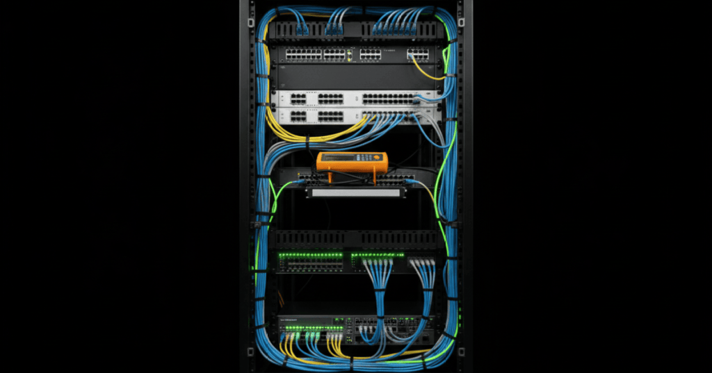
Structured cabling is the physical layer that connects servers, switches, storage, management networks, and out-of-band systems. In a data center, good cabling is not cosmetic: correct termination, labeling, routing, polarity, bend radius, and testing directly affect uptime and troubleshooting speed.
OSDCTC.003 continues the Open Source Data Center Technician sequence from OSDCTC.001: Data Center Safety — Rack Awareness, ESD, LOTO, and Hazards and OSDCTC.002: Rack Power Distribution — A/B Feeds, Rack PDUs, Dual-Corded Loads, and Load Checks. The sequence now adds the network side of rack-and-stack work: copper and fiber paths, patch panels, cable management, labeling, and physical-layer verification.
Structured cabling separates permanent infrastructure from service patching
A clean data-center cabling system separates permanent or semi-permanent infrastructure from short service patch cords. Instead of running an arbitrary cable directly across racks, technicians normally work through organized patch fields, trunks, horizontal/vertical managers, overhead or underfloor pathways, and documented endpoint relationships.
- Patch panel: organized termination or presentation point for copper or fiber circuits.
- Patch cord: flexible factory-made or approved short cable used between equipment and patching fields.
- Trunk: higher-density cable assembly carrying multiple copper pairs or multiple fibers between zones or racks.
- Horizontal manager: guides patch cords across a rack face.
- Vertical manager: routes cable bundles up and down rack sides.
- Pathway: ladder rack, tray, basket, raceway, underfloor path, or other approved support route.
The objective is traceability. A technician should be able to identify where a cable starts, where it ends, what service it carries, and how to replace or isolate it without disturbing unrelated connections.
Video 1: data center cabling architecture
Copper twisted-pair cabling
Twisted-pair Ethernet remains common for management networks, console servers, environmental devices, access switches, lower-speed server interfaces, and other equipment. Data-center deployments commonly use Category 6 or Category 6A systems depending on the required application, distance, shielding design, and site standard.
The category rating belongs to the complete channel or permanent-link design, not merely to the printing on the cable jacket. Cable, jacks, patch panels, patch cords, installation quality, pair geometry, and test results all matter.
T568B conductor order
When the site standard specifies T568B, the eight conductors are arranged by pin as follows:
- Pin 1: white/orange
- Pin 2: orange
- Pin 3: white/green
- Pin 4: blue
- Pin 5: white/blue
- Pin 6: green
- Pin 7: white/brown
- Pin 8: brown
Do not choose T568A or T568B by habit when working an existing facility. Follow the approved site drawing, patch-panel labeling, work order, and local standard. Mixing terminations unintentionally creates wiring faults and makes later troubleshooting harder.
Pair twist is part of the transmission system
The four twisted pairs are engineered to control crosstalk and electromagnetic susceptibility. Excessive untwisting at the jack, patch panel, or field termination degrades performance. Maintain pair geometry as close to the termination point as the connector and manufacturer procedure allow.
- Do not flatten, kink, crush, staple, or sharply bend data cable.
- Do not overtighten hook-and-loop straps around bundles.
- Avoid tight plastic zip ties where they deform cable geometry unless the site specifically approves them.
- Maintain separation from power conductors and noisy equipment according to the site design and applicable standards.
- Provide strain relief so connector contacts do not carry cable weight.
Patch-panel termination workflow
- Confirm the work order, rack, panel, port, and destination.
- Verify cable type and category against the panel and site standard.
- Route the cable through the approved pathway and manager before final termination when practical.
- Leave only the approved service loop; avoid large uncontrolled coils.
- Strip only the jacket length required for the termination.
- Preserve pair twists as close as possible to the IDC or jack contact.
- Terminate to the specified T568A or T568B color code.
- Secure strain relief without crushing the cable.
- Label both ends before the circuit disappears into a bundle.
- Wire-map and test before putting the link into service.
Wire map: the first copper sanity check
A wire-map test checks basic conductor continuity and pair arrangement. Typical faults include:
- open: one or more conductors are not electrically continuous;
- short: conductors make unintended contact;
- reversal: conductor order is reversed;
- crossed pair: conductors are landed on the wrong pair positions;
- split pair: continuity may appear correct pin-to-pin, but conductors from different twisted pairs are incorrectly combined, destroying intended pair geometry.
A simple continuity check can miss performance problems. A cable may pass basic wire map and still fail the required Ethernet application because of insertion loss, return loss, crosstalk, excessive length, poor termination, or pair damage.
Video 2: copper testing and T568B selection
Verification, qualification, and certification are not the same
Technicians should understand what level of test result a job actually requires.
- Verification: checks basic connectivity and wiring conditions such as wire map, continuity, length, and fault location.
- Qualification: evaluates whether a link can support a particular network application or data rate using the tester’s supported method.
- Certification: measures the installed cabling against a defined cabling standard and test limit using a certification-grade instrument.
Fluke Networks distinguishes these tester categories for different field tasks. A technician should never report a cable as “certified” when only a continuity or qualification test was performed. Fluke Networks’ cabling certification resources provide vendor guidance on certification-grade testing and result management.
Fiber in the data center
Fiber is heavily used for high-speed switch interconnects, storage fabrics, leaf-spine networks, cross-connects, long in-building runs, and high-density parallel-optics links. A technician must identify both the fiber type and the connector/polarity scheme before patching.
- Singlemode fiber: generally used where long reach, low attenuation, or high-speed optical architectures require it.
- Multimode fiber: common in shorter data-center links using compatible multimode transceivers.
- LC connectors: common duplex connector format for many optical transceivers and patch fields.
- MPO/MTP-style multifiber connectors: used for parallel optics and high-density trunks; polarity management becomes especially important.
Fiber polarity
Most duplex optical links require the transmitter at one end to reach the receiver at the other. A circuit can be physically connected and still remain down when polarity is wrong. Never “fix” polarity by randomly flipping fibers without documenting what changed.
- Confirm the expected A/B or Tx/Rx relationship.
- Check patch-panel and cassette labeling.
- Confirm trunk polarity method where MPO/MTP systems are used.
- Use approved polarity tools or light-source methods when documentation is uncertain.
- Record any authorized polarity change.
Inspect, clean, inspect, connect
Optical connector contamination is a major cause of loss and intermittent performance. Dust caps are protective but do not prove that an endface is clean.
- Confirm the fiber is safe to inspect under the approved procedure.
- Inspect the connector endface with the proper video inspection equipment when required.
- Clean with an approved fiber-optic cleaning method if contamination is present.
- Inspect again after cleaning.
- Mate only when the connector is acceptably clean.
- Protect unused ports and connectors.
The Fiber Optic Association FOA-8 inspection and cleaning standard provides a concise field reference for connector inspection, cleaning, and documentation.
Bend radius and pulling limits
Fiber cable must not be bent tighter than the manufacturer’s specified minimum radius. Exceeding bend limits can increase optical loss or permanently damage fibers and cable structure. Pulling tension, crush load, and storage radius also matter.
A commonly taught rule of thumb for conventional fiber cable is that the minimum bend radius may be approximately 20 times the cable diameter while under pulling tension and approximately 10 times the cable diameter after installation. This is not a universal substitute for the cable data sheet; always use the manufacturer’s actual specification for the installed cable.
Video 3: fiber-optic bend radius
Cable management is part of reliability
Good cable management prevents accidental disconnects, blocked airflow, crushed bundles, inaccessible components, and long outage times during troubleshooting.
- Keep patch cords out of fan intakes and hot exhaust paths.
- Do not route network cables across removable server components or service handles.
- Use horizontal and vertical managers instead of hanging loops from switch ports.
- Separate copper and fiber where the rack design provides dedicated pathways.
- Maintain enough slack for service without creating large unmanaged coils.
- Keep cable bundles from blocking rack PDU breakers, console ports, power supplies, blanking panels, or airflow paths.
- Never use a patch cord as mechanical support for another cable bundle.
Labeling standard
A useful label identifies a cable without requiring the technician to trace it by hand. Exact naming conventions vary by facility, but labels commonly encode source rack, source panel/port, destination rack, destination panel/port, circuit ID, or service identifier.
For example, a site might use a pattern such as R12-PP01-24 → R18-SW02-48. The example is illustrative only; use the facility’s approved convention.
- Label both ends.
- Place labels where they can be read without unplugging the cable.
- Use durable labels suitable for the environment.
- Make the database/DCIM record match the physical label.
- Update documentation during the same change window as the physical patch.
Rack patching workflow
- Read the ticket and confirm the exact source and destination.
- Validate rack, U position, device hostname, panel number, and port.
- Check whether the circuit is copper or fiber and identify the required connector/type.
- Confirm maintenance-window and change-control requirements.
- Inspect both target ports before moving any existing cable.
- Label the new patch cord before final routing when possible.
- Route through approved managers while preserving bend radius and airflow.
- Connect source and destination without disturbing adjacent ports.
- Verify link state and expected speed.
- Run the required physical-layer test.
- Update the ticket, port map, and DCIM/documentation.
- Retain rollback information until the change is accepted.
Do not trust link lights alone
A link LED proves only that the connected interfaces detected enough signaling to establish a link under current conditions. It does not prove that the cable is correctly documented, certified to the required limit, free of intermittent faults, operating at the intended speed, or patched to the intended destination.
Physical-layer troubleshooting sequence
- Confirm the intended endpoint pair from documentation.
- Check link LEDs and interface status.
- Inspect patch cords for damage, sharp bends, crushed sections, loose latches, and incorrect routing.
- For copper, run wire map and length/distance-to-fault checks.
- Confirm T568A/T568B termination consistency where field terminations are involved.
- For fiber, verify connector type, fiber type, polarity, and transceiver compatibility.
- Inspect and clean fiber endfaces as required.
- Swap only with a known-good, correctly rated patch cord when change control allows.
- Test the permanent link or channel to the required level if the fault remains.
- Document the fault and corrective action before closing the ticket.
Common workmanship defects
- copper pairs untwisted too far from the termination;
- wrong T568 pinout;
- split pairs;
- patch cords stretched tightly between ports;
- excessive fiber bend;
- dirty optical connectors;
- incorrect fiber polarity;
- unlabeled cords;
- labels that disagree with DCIM or drawings;
- cables blocking airflow or service access;
- mixed cable categories or unsupported patch components;
- temporary patches left in place permanently without documentation.
Exercises
- Write the eight T568B conductor colors in pin order from memory.
- Explain why a split pair can pass a simple continuity check yet still be a serious Ethernet fault.
- Describe the difference between verification, qualification, and certification testing.
- Create a labeling scheme for a two-row lab with four racks per row.
- Design a patching workflow that includes rollback information.
- Explain why optical polarity must be documented rather than corrected by random fiber swapping.
- Calculate 10× and 20× bend-radius values for a cable with a 7 mm outside diameter, then explain why the manufacturer data sheet still takes precedence.
- List five ways poor cable management can create an outage or extend repair time.
- Develop a copper troubleshooting sequence for a link that negotiates at 100 Mb/s instead of 1 Gb/s.
- Develop a fiber troubleshooting sequence for a link that remains down after a switch replacement.
Knowledge check and answers
1. What are pins 1 and 2 in T568B?
White/orange on pin 1 and orange on pin 2.
2. Why should twisted pairs remain twisted close to the termination?
The pair geometry is part of the cable’s crosstalk and noise-control performance.
3. Does a successful wire map prove that a cable meets Category 6A performance?
No. Wire map verifies conductor arrangement and continuity conditions; certification requires additional performance measurements against the required test limit.
4. Why are fiber connectors inspected and cleaned before mating?
Dirt and contamination can create optical loss, reflectance problems, and physical endface damage.
5. What is the purpose of bend-radius control?
To prevent excessive optical loss and mechanical damage caused by bending cable more tightly than its design permits.
6. Why label both ends of a cable?
So either endpoint can be identified and traced without disconnecting or physically following the entire route.
7. What is a split pair?
A wiring error where conductors are placed on the correct pin numbers for continuity but are taken from the wrong physical twisted pairs, severely degrading transmission performance.
8. Why is a link light insufficient final verification?
It does not prove correct destination, documentation, required cable performance, intended link speed, or freedom from intermittent physical-layer faults.
Key takeaway
Data-center cabling work is controlled physical-layer engineering. Copper termination must preserve pair geometry and the approved pinout; fiber work must preserve polarity, cleanliness, and bend radius; patching must preserve airflow, traceability, and service access; and testing must match the actual acceptance requirement. A cable is not complete when it is plugged in—it is complete when it is correctly routed, labeled, tested, documented, and recoverable.
Display note: this lesson uses standard responsive Gutenberg paragraphs, lists, and embeds rather than fixed-width decorative text boxes or wide tables.
BitcoinVersus.Tech
Advertisement
Editor’s Note:
We volunteer daily to ensure the credibility of the information on this platform is Verifiably True. If you would like to support our research initiatives, please donate here: 3C9o19EH5HSiwEPyCTmEKzxhNCbo2X6TTb
BitcoinVersus.tech is not a financial advisor. This media platform reports on financial subjects purely for informational purposes.


Leave a Reply