Elementary Overview
A fiber optic connector is the removable end of a fiber cable that lets light pass from one cable or device into another. The connector must match physically, the fiber type must match the optical system, and the transmit side must eventually reach the receive side. Technicians therefore need to recognize connector families such as LC, SC, and MPO/MTP, understand the difference between UPC and APC end faces, and verify polarity before calling a link complete. This lesson builds on OSFOTC.002 optical power testing and OSFOTC.003 OTDR testing.
Recognize the Connector Before You Patch It
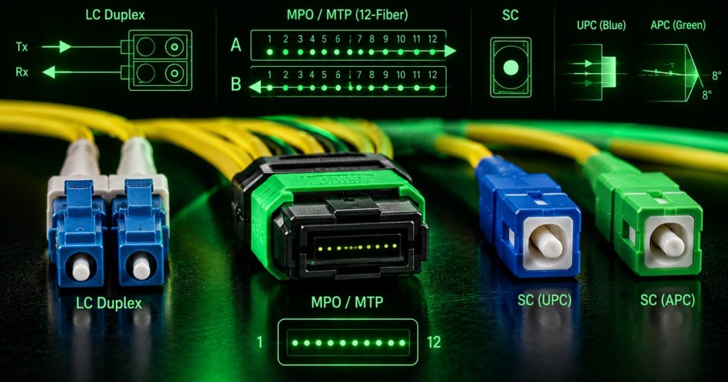
LC uses a small 1.25 mm ferrule and is common on modern optical transceivers and dense data-center panels. SC uses a larger 2.5 mm ferrule and a push-pull body. Older environments may also use ST or FC connectors. MPO is a multifiber array connector used when many fibers must be connected at once; MTP is a commercial high-performance implementation of the MPO interface. A technician should verify connector type, adapter type, ferrule condition, fiber type, and cable labeling before insertion. Never force a connector that does not seat naturally, and use the cleanliness practices introduced in OSFOTC.001 before every mating operation.
UPC and APC Describe the Polished End Face
UPC means Ultra Physical Contact and uses a highly polished end face that meets the opposite ferrule nearly perpendicular to the fiber axis. APC means Angled Physical Contact and commonly uses an approximately 8° angled end face so reflected light is directed away from the fiber core. Blue housings commonly identify UPC single-mode connectors, while green commonly identifies APC, but the label and equipment specification are more authoritative than color alone. Do not mate APC directly to UPC: the end-face geometries do not match correctly, which can create high loss, poor return loss, and possible ferrule damage.
Duplex Polarity Means Tx Must Reach Rx
Most duplex optical links use one fiber for transmit (Tx) and another for receive (Rx). The channel is correct only when the transmitter at one end reaches the receiver at the other. In an LC duplex link, this usually means the fiber pair crosses somewhere in the channel. A cable that is physically connected but has Tx landing on Tx will show no working link even if optical loss on each individual fiber is otherwise acceptable. That is why patch-panel labeling, fiber identification, and structured-cabling documentation matter as much as connector insertion.
MPO/MTP Polarity Adds Fiber Numbering and Key Orientation
An MPO/MTP connector carries many fibers in one ferrule, so polarity is more complicated than simply swapping an LC duplex pair. Technicians must pay attention to fiber positions, key orientation, pin/no-pin gender, cassette or breakout mapping, and the polarity method specified by the cabling design. A 12-fiber trunk can be physically mated yet still place lanes in the wrong order for a parallel-optics link. The practical rule is to treat polarity as a property of the entire channel—not one patch cord by itself—and verify the documented mapping before changing any cassette, trunk, or breakout component.
Use a VFL for Continuity, Identification, and Simple Polarity Checks
A visual fault locator (VFL) injects visible red laser light into a fiber. It is useful for identifying which fiber appears at the far end, checking continuity, confirming a duplex pair, and finding some severe bends, breaks, or bad connections that leak visible light. A VFL does not replace an optical power meter or OTDR; it answers simpler visual questions quickly. Never look into a fiber or VFL output, even when the visible beam seems weak. For duplex polarity, launch the VFL into the intended Tx-side fiber and confirm that the expected opposite-side connector receives the light before connecting active optics.
Technician Verification Workflow
- Read the work order and identify the expected connector type, fiber type, transceiver, and port mapping.
- Confirm whether each end requires LC, SC, MPO/MTP, or another connector family.
- Confirm UPC versus APC before mating single-mode connectors.
- Inspect and clean both connector end faces before insertion.
- Verify patch-panel labels and destination ports against the structured-cabling record.
- For duplex links, confirm Tx at one end reaches Rx at the other.
- For MPO/MTP links, verify the required key orientation, fiber map, cassette type, and polarity method.
- Use a VFL for continuity or identification when appropriate.
- Measure receive power or insertion loss when the acceptance procedure requires quantitative proof.
- Use the OTDR when fault location, event loss, or distance information is needed.
- Record the final port-to-port mapping and test result.
Exercises
- Identify an LC, SC, and MPO connector from photographs or physical samples.
- Explain why an APC connector should not be directly mated to a UPC connector.
- Draw a duplex link showing Tx at device A reaching Rx at device B and vice versa.
- Describe how you would use a VFL to identify one unknown fiber in a patch panel.
- List four items that must be checked before replacing an MPO trunk or cassette.
- Explain why correct optical power does not automatically prove that a duplex link has correct logical polarity.
Knowledge Check + Answers
- What is the main practical advantage of LC? Its small form factor allows high connector density in modern network and data-center equipment.
- What does APC change? It angles the polished end face so reflected light is directed away from the core.
- What is duplex polarity? The mapping that ensures each transmitter reaches the receiver at the opposite end.
- Why is MPO/MTP polarity more complicated? Many fibers share one connector, so fiber position, key orientation, pinning, cassettes, and breakout mapping all matter.
- What does a VFL prove well? Visual continuity, fiber identity, and some obvious bends or breaks.
- What does a VFL not replace? Quantitative optical-power or insertion-loss testing and OTDR fault-location measurements.
Elementary Conclusion
Fiber connectors are like carefully shaped doors for light. LC and SC describe the shape of the connector body, UPC and APC describe how the tiny glass end is polished, and polarity describes whether the light is traveling into the correct fiber at the correct destination. A fiber can look perfectly connected and still fail because the wrong connector polish was used, Tx was routed back to Tx, or an MPO fiber lane was mapped incorrectly. A good technician therefore checks the connector, cleans it, confirms the route, verifies polarity, and then measures the optical signal. The goal is not simply to make the plug fit; it is to make the correct light arrive at the correct receiver with acceptable loss.
BitcoinVersus.Tech
Advertisement
Editor’s Note:
We volunteer daily to ensure the credibility of the information on this platform is Verifiably True. If you would like to support our research initiatives, please donate here: 3C9o19EH5HSiwEPyCTmEKzxhNCbo2X6TTb
BitcoinVersus.tech is not a financial advisor. This media platform reports on financial subjects purely for informational purposes.


Leave a comment