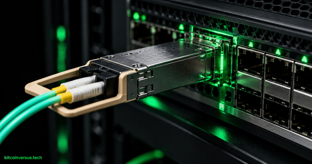
Optical transceiver selection is the process of matching a pluggable optical module to a host port, a fiber plant, a required data rate, and an end-to-end optical performance target. A module can fit physically and still be wrong electrically, optically, thermally, or operationally.
OSFOEC.003 follows OSFOEC.002: Fiber Dispersion Engineering — Modal, Chromatic, PMD, Pulse Broadening, and Reach Limits and OSFOEC.001: Optical Link Budget Engineering — dB, Power Budget, Loss Budget, and Design Margin. The field-measurement side connects to OSFOTC.003: OTDR Field Testing.
Learning objectives
- Distinguish optical form factor from Ethernet speed and optical reach.
- Match SFP, QSFP, QSFP-DD, and OSFP families to compatible host ports.
- Select the correct fiber type, wavelength plan, connector type, and lane architecture.
- Check both optical loss margin and receiver overload.
- Include dispersion, FEC, breakout behavior, temperature, power, and module management in the design.
- Separate standards-based optical interoperability from vendor-specific host compatibility.
- Use digital optical monitoring data as evidence rather than as a replacement for proper test equipment.
- Build a repeatable engineering workflow for transceiver qualification.
What an optical transceiver does
An optical transceiver converts electrical data from a switch, router, server, storage system, or transport platform into modulated light. At the far end, another transceiver converts the received light back into electrical data.
The module therefore sits between two different engineering domains. Its host side must match an electrical interface and protocol, while its line side must match a fiber type, connector system, wavelength plan, optical budget, and reach requirement.
Selection is a constraint-matching problem
Correct selection begins with the complete link requirement rather than with the label printed on the module. The engineer should define the host port, line rate, lane structure, media, connector, distance, loss, temperature, and interoperability requirement before selecting a part number.
host port
  + protocol / data rate
  + electrical lane interface
  + fiber type
  + connector / polarity
  + wavelength architecture
  + distance and channel loss
  + dispersion tolerance
  + FEC behavior
  + power / thermal envelope
  + management interface
  + platform support
  = valid transceiver choice
Common pluggable form-factor families
A form factor defines the mechanical package and host connector family. It does not, by itself, define one specific data rate or optical standard.
| Family | Common engineering role | Important caution |
|---|---|---|
| SFP / SFP+ / SFP28 / SFP56 | Single-lane pluggables used across many 1G, 10G, 25G, and 50G applications | A physically similar cage does not guarantee support for every SFP-family speed or coding method. |
| QSFP+ / QSFP28 | Four-lane pluggables widely used for 40G and 100G systems and breakout applications | Lane mapping, breakout support, connector type, and FEC vary by standard. |
| QSFP-DD | Double-density QSFP family used for high-density 400G and 800G systems | Host electrical generation, thermal class, firmware, and backward compatibility must be verified. |
| OSFP | Larger high-power form factor used for 400G, 800G, and higher-speed implementations | An OSFP module cannot be assumed to fit or operate in a QSFP-DD cage. |
Cisco describes QSFP-DD as a high-density form factor that increases the number of high-speed electrical interfaces while supporting 400G and 800G applications. Its current optics portfolio also illustrates an important rule: one form factor can support copper, multimode, single-mode, PAM4, and coherent implementations, so form factor alone is never enough for selection. Cisco QSFP-DD optical transceiver overview.
Video: SFP transceiver fundamentals
Host-port compatibility comes first
The host device determines which electrical interfaces, speeds, lane counts, and module-management methods are supported. A module that is optically correct can still fail if the switch ASIC, line card, cage, firmware, or port configuration does not support it.
Platform compatibility matrices should therefore be treated as design inputs, not as after-installation troubleshooting documents. The check should include the exact hardware revision, software release, breakout mode, FEC mode, and module part number where the vendor requires that level of specificity.
Data rate and lane architecture
High-speed Ethernet does not always send the full port rate as one optical lane. A 400G module may use four optical lanes, eight optical lanes, one coherent carrier, or another architecture depending on the specification.
This is why two modules with the same aggregate rate are not automatically interchangeable. Their host electrical lanes, optical lane count, wavelength plan, FEC relationship, and fiber connector can be completely different.
Fiber type: multimode and single-mode
Multimode fiber is widely used for short-reach data-center links, often with 850 nm optics. Single-mode fiber is used for longer reach, lower modal dispersion, and wavelength architectures around 1310 nm and the 1550 nm region.
The fiber already installed in the plant may determine which module families are practical. Converting a port from one optic to another does not convert the underlying cable plant from multimode to single-mode or correct a connector and polarity mismatch.
Wavelength architecture
Wavelength is part of the optical standard. Short-reach multimode systems commonly operate near 850 nm, while many single-mode data-center standards use wavelengths near 1310 nm.
Longer-reach and wavelength-division systems may use multiple CWDM wavelengths or tunable C-band coherent carriers. A receiver designed for one wavelength plan should not be assumed to interoperate with a module that uses a different optical grid or multiplexing method.
Connector type and polarity
Many serial or wavelength-multiplexed optics use duplex LC connectors, while parallel optics commonly use MPO-family connectors. Connector type is therefore tied to the lane architecture as well as the physical patching method.
Multifiber systems also require correct polarity. An optical design can have the right module and the right fiber type and still fail because transmit lanes do not arrive at the intended receive lanes.
Reach is an operating envelope
A stated reach such as 100 m, 500 m, 2 km, 10 km, or 80 km is not simply a promise that light travels that far. The value usually assumes a defined fiber type, connector system, maximum channel loss, transmitter quality, receiver performance, dispersion limit, and FEC behavior.
The engineer should therefore read the standard or manufacturer optical specification instead of choosing a module from distance alone. A short physical route can still fail if connector loss, reflectance, polarity, excessive launch power, or the wrong fiber type violates the operating envelope.
Power budget and insertion-loss margin
The first optical check is whether sufficient power reaches the receiver. The channel insertion loss must remain below the loss allowed by the selected optical specification.
channel loss = fiber loss + connector loss + splice loss + passive-component loss

remaining channel margin = allowed channel loss - measured or predicted channel loss
The earlier OSFOEC.001 lesson develops this calculation in detail. Transceiver selection uses that same budget as one part of the decision rather than treating the module’s advertised reach as a substitute for engineering the actual channel.
Receiver overload matters too
More received optical power is not always better. Every receiver has an upper input limit, and a very short low-loss link can exceed the allowed receive power of a long-reach optic.
The complete power check therefore has two sides: the minimum received power must remain above the sensitivity requirement, while the maximum received power must remain below overload. Engineers should use the exact transmit and receive limits for the selected module and standard.
Dispersion remains a separate limit
A link can pass its optical power budget and still fail because the waveform has broadened too much. Chromatic dispersion, modal effects, polarization-mode dispersion, and transmitter chirp can reduce the usable eye opening even when average receive power is acceptable.
OSFOEC.002 explains these reach limits. Transceiver selection must therefore satisfy both the power budget and the time-domain or dispersion budget.
Forward error correction
Forward error correction (FEC) adds redundancy so the receiver can correct a defined amount of transmission error. Many high-speed Ethernet optical interfaces rely on FEC as part of the normal link design rather than as an optional rescue mechanism.
The host and optic must agree on the expected FEC architecture. A link can remain down even when optical power is present if the endpoints use incompatible FEC, lane, PCS, or port-mode settings.
Breakout optics
A high-rate port can sometimes be divided into several lower-rate links. For example, a 400G host port may support four 100G channels when the platform, module, cable plant, and remote optics all support the same breakout architecture.
Cisco’s current 400G QSFP-DD portfolio documents multiple 400G-to-100G breakout combinations and shows that the allowed reach depends on the exact pair of optical standards. Cisco 400G QSFP-DD cable and transceiver data sheet.
Standards interoperability and host compatibility are different
Two modules can be optically interoperable under the same Ethernet standard while one host platform still rejects an unsupported module identifier. The optical standard governs line behavior, while the platform vendor may separately enforce coding, qualification, firmware, or inventory rules.
Engineering validation should therefore ask two questions. First, do the optical interfaces comply with compatible specifications; second, do both host platforms support the exact modules and operating mode being deployed?
Video: 400G multivendor interoperability
Digital optical monitoring
Modern pluggable optics commonly expose telemetry such as module temperature, supply voltage, transmit power, receive power, bias current, alarms, and lane-level status. The management model may use SFF-family definitions, CMIS, or another platform-supported interface.
Telemetry is valuable because it lets engineers compare live operating conditions with specification limits. It should not replace calibrated optical test equipment when acceptance testing or fault isolation requires an independent measurement.
Thermal and power limits
Higher-speed optics can consume significant electrical power and generate substantial heat inside a dense switch front panel. A module that is optically and electrically compatible can still be a poor design choice if the platform cannot cool it within the allowed case-temperature range.
Thermal validation should consider airflow direction, port density, ambient inlet temperature, heatsink design, neighboring modules, and the module’s maximum power class. This becomes increasingly important at 400G, 800G, coherent, and other high-power pluggable rates.
Coherent pluggable optics
Coherent optics use advanced modulation, local oscillators, digital signal processing, and strong FEC to support much longer reach and tighter spectral use than ordinary short-reach direct-detect optics. Modern coherent modules can place metro and transport functions directly into router and switch pluggable ports.
Cisco’s current 100G ZR and higher-rate coherent products illustrate how tunable C-band wavelength, FEC, reach, power consumption, host management, and platform support all become part of the transceiver-selection problem. Cisco QSFP28 100G ZR coherent optics data sheet.
Worked example: a 400G link over 1.2 km of single-mode fiber
Assume two switches provide supported 400G QSFP-DD ports. The installed plant is 1.2 km of single-mode fiber with duplex LC connectivity, and the measured end-to-end channel insertion loss is 2.7 dB.
A 400GBASE-FR4-style solution is a logical candidate because that class is designed for kilometer-scale single-mode operation over duplex fiber. A specific Cisco FR4 implementation lists a 2 km reach and a 4 dB maximum supported insertion loss, so a 2.7 dB measured channel would leave 1.3 dB of channel-loss margin before any project-specific engineering reserve is added.
allowed channel loss = 4.0 dB
measured channel loss = 2.7 dB
remaining channel-loss margin = 4.0 - 2.7 = 1.3 dB
The calculation does not finish the design. The engineer must still verify both host compatibility lists, FEC behavior, connector cleanliness, temperature range, module power, wavelength specification, receiver limits, and the exact standard or manufacturer requirements for the chosen part numbers.
A repeatable transceiver-selection workflow
- Identify both endpoint platforms, line cards, port types, and software versions.
- Define the required Ethernet or transport rate and the lane or breakout architecture.
- Confirm the host supports the required module form factor and electrical interface.
- Identify the installed fiber type, connector type, polarity, and route length.
- Choose the optical standard or application code that matches the media and reach.
- Calculate or measure the complete channel insertion loss.
- Check receiver sensitivity, maximum receive power, and allowed channel loss.
- Check chromatic, modal, and PMD limits where they are relevant.
- Confirm FEC mode, PCS behavior, and breakout configuration.
- Verify wavelength plan, optical lane count, and connector architecture.
- Check module power, cooling, and allowed operating temperature.
- Verify module-management support, diagnostics, and alarm interpretation.
- Confirm standards interoperability and each platform’s vendor-support matrix.
- Validate the assembled link with optical measurements and traffic or BER testing appropriate to the system.
Testing an installed transceiver
Initial field checks should confirm that the module is recognized, enabled, and transmitting. Live-fiber detection, DOM values, optical power measurement, inspection, and traffic testing can then narrow the problem to the module, host, patching, fiber plant, or remote endpoint.
A non-contact live-fiber detector is useful for confirming that an SFP or QSFP is emitting light without viewing the fiber end face. It does not prove that the wavelength, power level, modulation, FEC, lane mapping, or data path is correct.
Video: testing SFP and QSFP optical output
Common engineering mistakes
- Selecting by physical form factor without checking the host electrical interface.
- Selecting by distance only and ignoring channel loss, receiver overload, or dispersion.
- Using a multimode optic on single-mode plant or the reverse.
- Assuming duplex LC and MPO parallel optics are directly interchangeable.
- Ignoring connector polarity in parallel-fiber systems.
- Assuming two 400G optics interoperate simply because both are labeled 400G.
- Ignoring the FEC or breakout mode required by the optical standard.
- Using third-party optics without checking the host platform’s support policy and module coding.
- Ignoring module power and front-panel thermal density.
- Treating DOM receive power as a substitute for calibrated acceptance testing.
- Forgetting to verify maximum receive power on very short links.
- Choosing long-reach optics for short links without checking whether attenuation is required.
Exercises
- Create a selection table for 10G, 25G, 100G, 400G, and 800G ports that separates form factor from optical reach.
- Explain why a QSFP28-shaped module cannot be assumed to operate in every QSFP-family host port.
- For a 1.5 km single-mode route with duplex LC patching, list the information needed before choosing a 400G optic.
- Design a checklist that verifies both minimum receive power and receiver overload.
- Compare a parallel-MPO 400G architecture with a duplex-LC wavelength-multiplexed 400G architecture.
- Describe how a breakout link changes the host-port, module, cabling, and remote-end requirements.
- Explain how FEC mismatch can create a dead link even when optical power is present.
- Build a qualification plan for a third-party transceiver that includes host support, temperature, optical budget, DOM, traffic, and BER testing.
Knowledge check
1. Does form factor define optical reach?
No. Form factor defines the physical module and host interface family. Reach is defined by the optical standard, fiber, power budget, dispersion tolerance, and related operating limits.
2. Why must host compatibility be checked separately from optical interoperability?
Two modules can use compatible line-side optics while a switch or router still rejects an unsupported module, speed, firmware, power class, or management interface.
3. What are the two sides of the receiver power check?
Received power must be high enough to remain above the minimum sensitivity requirement and low enough to remain below the receiver overload limit.
4. Why can a link pass its power budget and still fail?
Dispersion, FEC mismatch, lane mapping, polarity, excessive reflection, host incompatibility, or other signal-quality limits can prevent correct data recovery.
5. Why is connector type an engineering input?
It reflects the optical lane architecture and plant interface. Duplex LC, MPO parallel optics, and other connector systems are not interchangeable without a compatible optical design.
6. What is the purpose of DOM or digital optical monitoring?
It provides live module telemetry such as temperature, voltage, transmit power, receive power, alarms, and lane status for monitoring and troubleshooting.
7. Why is thermal design part of transceiver selection?
High-speed modules can consume substantial power. Excess case temperature can reduce reliability, trigger alarms, or force the host to disable the module even when the optical design is otherwise correct.
8. What must be verified before using a breakout optic?
The host port, module, software configuration, lane mapping, FEC, cable plant, remote optics, and reach must all support the same breakout architecture.
Key takeaway
Optical transceiver selection is an end-to-end engineering task. The correct module must fit the host, support the required electrical and optical rate, match the fiber and connector plant, operate at the correct wavelength, satisfy loss and dispersion limits, use compatible FEC and lane mapping, remain within thermal limits, and interoperate with the remote endpoint.
A reliable design therefore does not begin with the question “Which optic reaches this distance?” It begins with a complete definition of the port, media, signal, environment, and interoperability requirements, followed by a documented verification of every constraint.
Engineering note: The example specifications are instructional. Production designs must use the current IEEE, OIF, MSA, vendor, platform-support, module-management, safety, temperature, power, FEC, fiber, and optical-performance requirements applicable to the exact equipment being deployed.


Leave a Reply