Elementary Overview
A fiber link does not send whole files as one giant flash of light. It sends a rapid sequence of symbols. A simple signaling method called NRZ uses two levels, so each symbol can represent one bit. PAM4 uses four levels, so one symbol can represent two bits. That lets an optical link carry more data without doubling its symbol rate, but the four levels sit closer together and are therefore harder for the receiver to distinguish when noise, loss, reflections, or dispersion distort the signal. This lesson follows OSFOEC.003 optical transceiver selection by explaining what the transceiver is actually encoding onto the optical channel.
NRZ Uses Two Levels; PAM4 Uses Four
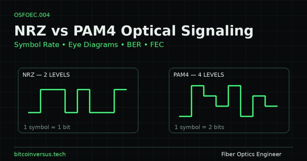
NRZ, or non-return-to-zero signaling, normally represents binary 0 and 1 with two amplitude levels. PAM4, or four-level pulse-amplitude modulation, represents four amplitude states and therefore carries log₂(4)=2 bits per symbol. A 53.125 GBd PAM4 lane can therefore carry roughly 106.25 Gb/s of raw information before coding overhead, while a 53.125 GBd NRZ lane carries roughly 53.125 Gb/s. PAM4 is one reason modern 100G-per-lane, 400G, and 800G optical interfaces can increase throughput without requiring the analog front end to run at twice the baud rate. The price is reduced vertical separation between decision levels, which lowers noise margin and makes transmitter linearity, receiver sensitivity, equalization, and channel quality more important.
Symbol Rate Is Not the Same as Bit Rate
Baud rate measures symbols per second, while bit rate measures information bits per second. For an uncoded modulation with M possible symbol states, the ideal relationship is bit rate = symbol rate × log₂(M). NRZ has M=2; PAM4 has M=4. Real Ethernet optics also include coding and forward error correction overhead, so line rate, payload rate, lane rate, and baud rate should not be treated as interchangeable numbers. Engineers use this distinction when selecting optical transceivers, checking SerDes compatibility, estimating bandwidth requirements, and determining whether a given optical lane architecture can support the target Ethernet rate.
Eye Diagrams Show Timing and Amplitude Margin
An eye diagram overlays many symbol intervals so engineers can see the statistical opening available to a receiver. NRZ produces one principal eye opening; PAM4 produces three stacked eyes because four voltage or optical-power levels create three decision thresholds. A wider horizontal opening generally means more timing margin, while a larger vertical opening means more amplitude margin. Eye closure can come from bandwidth loss, jitter, noise, reflections, inter-symbol interference, dispersion, poor equalization, or transmitter defects. In optical PAM4 standards, engineers often use measurements such as TDECQ in addition to the visual eye because a pretty picture alone does not prove standards compliance.
BER Turns Signal Quality Into a Reliability Number
Bit error rate (BER) is the number of incorrectly received bits divided by the total number of transmitted bits. A BER of 10−6 means roughly one errored bit per million bits; high-speed optical systems often need much lower post-FEC error rates. Engineers distinguish pre-FEC BER, measured before the error-correction decoder, from post-FEC BER, measured after correction. Pre-FEC BER reveals how hard the physical channel is working, while post-FEC BER tells whether the delivered data meets the required reliability target. Optical receive power from power-meter testing is important, but two links with similar received power can have different BER if dispersion, reflections, noise, or transmitter quality differ.
FEC Trades Redundancy for a Lower Delivered Error Rate
Forward error correction (FEC) adds structured redundant information so the receiver can detect and correct a limited number of errors without requesting retransmission. This is especially valuable in high-speed Ethernet optics because PAM4 operates with smaller level spacing than NRZ and can tolerate a higher raw error rate when a specified FEC scheme is part of the interface. FEC is not free: parity symbols consume bandwidth, decoding adds latency and power, and every code has a correction limit. If pre-FEC BER rises beyond the code’s capability, post-FEC performance can collapse quickly. Engineers therefore treat FEC as part of the link architecture rather than as permission to ignore poor optical margin or bad fiber connections and polarity.
PAM4 Is a System-Level Tradeoff, Not Automatically Better Signaling
PAM4 improves spectral efficiency by carrying two bits per symbol, but it also makes the signal more sensitive to noise and nonlinearity. NRZ can still be preferable where the required lane rate, reach, power, and cost do not justify four-level signaling. Modern optical modules combine high-speed SerDes, modulators, photodetectors, DSP, FEC, clock recovery, packaging, and increasingly advanced semiconductor and optical integration. That system-level view is important: higher efficiency often comes from putting the right semiconductor, photonic, packaging, and coding technologies together rather than demanding that one device or material perform every function. The same idea appears in single-wavelength 100G optics and in the broader move toward silicon photonics and heterogeneous integration.
Worked Example: 100 Gb/s Raw Lane Target
- NRZ: 1 bit/symbol, so approximately 100 GBd would be required for 100 Gb/s before coding overhead.
- PAM4: 2 bits/symbol, so approximately 50 GBd would carry 100 Gb/s before coding overhead.
- Engineering benefit: the required symbol rate is roughly halved.
- Engineering cost: four amplitude levels reduce vertical decision margin and increase sensitivity to noise and distortion.
- System response: stronger transmitter/receiver linearity, equalization, measurement, and FEC are used to recover reliable data.
Engineering Checklist
- Identify the required payload rate, line rate, lane count, and symbol rate.
- Confirm whether each electrical and optical lane uses NRZ, PAM4, or another modulation.
- Calculate bits per symbol using log₂(M).
- Verify transceiver, host SerDes, fiber type, wavelength, and reach compatibility.
- Check link budget and dispersion margin from OSFOEC.001 and OSFOEC.002.
- Inspect the eye or standards-defined transmitter metric.
- Measure pre-FEC BER under realistic temperature and channel conditions.
- Confirm the required FEC mode on both ends of the link.
- Verify post-FEC performance and monitor corrected/uncorrectable codeword counters.
- Do not accept a link solely because received optical power is inside the nominal range.
Exercises
- Calculate the uncoded bit rate of a 26.5625 GBd NRZ lane.
- Calculate the uncoded bit rate of a 26.5625 GBd PAM4 lane.
- Explain why PAM4 reduces required baud rate but reduces amplitude margin.
- Sketch an NRZ eye and a PAM4 eye and label the decision thresholds.
- Explain the difference between pre-FEC BER and post-FEC BER.
- Describe a case where optical receive power is acceptable but BER is still poor.
- Explain why FEC cannot rescue an arbitrarily bad optical channel.
- List three reasons an engineer might still select NRZ instead of PAM4.
Knowledge Check + Answers
- How many bits does one PAM4 symbol represent? Two bits.
- What is baud? Symbols per second.
- Why does PAM4 have three eyes? Four amplitude levels create three decision boundaries.
- What does BER measure? The fraction of received bits that are incorrect.
- What is pre-FEC BER? The raw error rate before the FEC decoder corrects errors.
- What does FEC add to the transmission? Structured redundancy that lets the receiver detect and correct a limited number of errors.
- Does acceptable received optical power guarantee a good link? No. Dispersion, noise, reflections, modulation quality, and other impairments can still produce excessive BER.
Elementary Conclusion
NRZ is like sending information with a light that has only two clearly different choices. PAM4 uses four choices, so each signal can carry twice as many bits, but the choices are closer together and easier to confuse. Engineers use eye diagrams to see whether those choices are still separated, BER to count how often the receiver guesses wrong, and FEC to repair a limited number of those mistakes. The useful lesson is that faster fiber is not created by one trick. Modern links combine better modulation, better optics, better semiconductors, better signal processing, and better error correction so more information can move through the same physical channel without losing reliability.
BitcoinVersus.Tech
Advertisement
Editor’s Note:
BitcoinVersus.Tech publishes independent technical education and research. Readers can support the project through the donation information already published on the site.
BitcoinVersus.tech is not a financial advisor. This media platform reports on financial subjects purely for informational purposes.


Leave a comment