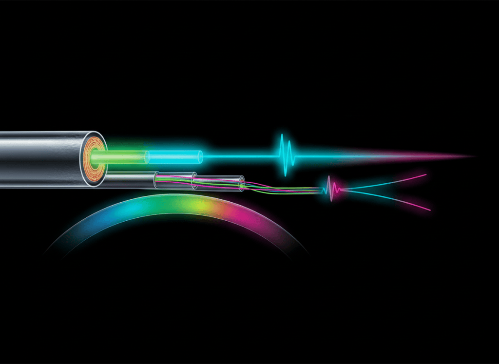
Optical power determines whether enough light reaches a receiver. Dispersion determines whether the information carried by that light remains distinguishable when it arrives. As pulses broaden, adjacent symbols begin to overlap, the eye closes, timing margin shrinks, and a link can fail even when received power is still above sensitivity.
OSFOEC.002 continues the Open Source Fiber Optics Engineer Certification track from OSFOEC.001: Optical Link Budget Engineering — dB, Power Budget, Loss Budget, and Design Margin. The prior lesson established attenuation and optical margin. This lesson develops the second major reach limit: time-domain spreading of optical signals.
The technician-level measurement foundation appears in OSFOTC.002: Optical Power Meter Basics — dBm, Wavelength, Reference Levels, and Receive Power. Power meters verify amplitude. Dispersion engineering determines whether pulse shape and timing remain usable at the intended bit rate and distance.
The dispersion model
launch a finite-width optical pulse → different modes, wavelengths, or polarization states propagate with different delays → the received pulse becomes wider → adjacent symbols move closer together in time → intersymbol interference increases → receiver margin falls → maximum reliable reach decreases
Dispersion is different from attenuation
Attenuation reduces optical power. Dispersion spreads optical energy in time. A link can therefore have adequate received dBm and still fail because the detector can no longer separate one symbol from the next.
In a digital system, the bit period is approximately:
Tb = 1 / Rb
At 10 Gb/s, the bit period is about 100 ps. At 100 Gb/s per lane, the symbol timing is much tighter and the tolerance for accumulated spreading is correspondingly smaller, depending on modulation format, equalization, FEC, and receiver design.
MIT: Optical fibers as waveguides
Group velocity and group delay
An optical carrier oscillates extremely rapidly, but digital information is carried by the envelope of the modulated signal. The velocity of that envelope is the group velocity.
Group delay through a fiber length can be written conceptually as:
τg = L / vg
If different components of the signal have different group velocities, they arrive at different times. Dispersion is fundamentally the accumulation of those differential delays.
Modal dispersion
Modal dispersion occurs in multimode fiber because different guided modes can follow different effective paths and experience different transit times.
In a simple step-index model, higher-order modes travel more oblique paths than lower-order modes. The same launched pulse therefore arrives as a broader distribution of energy at the far end.
Graded-index multimode fiber reduces modal delay by varying the refractive index across the core. Rays that travel longer geometric paths spend more of their path in lower-index regions and move faster, reducing differential mode delay compared with a simple step-index design.
MIT: Dispersion as pulse spreading
Bandwidth-distance product
Multimode fiber is often characterized by a bandwidth-distance relationship. A simplified engineering interpretation is that longer links support less analog modulation bandwidth when modal dispersion dominates.
A rough relationship can be written as:
B × L ≈ constant
This is not a universal transceiver reach formula. Real Ethernet and Fibre Channel reaches depend on launch conditions, effective modal bandwidth, transmitter encircled flux, receiver equalization, coding, and the applicable standard. The relationship is still useful for understanding why multimode reach decreases as symbol rate increases.
MIT: Modal dispersion in multimode fiber
Chromatic dispersion
Chromatic dispersion occurs because different wavelength components of an optical signal do not all propagate with exactly the same group delay.
Even a laser has finite spectral width. If wavelengths on one side of the spectrum travel slightly faster than wavelengths on the other side, an initially narrow pulse broadens as distance increases.
Chromatic dispersion is commonly described by the coefficient D, with units of ps/(nm·km).
A useful first-order estimate is:
Δt ≈ |D| × L × Δλ
- Δt: pulse spreading in picoseconds
- D: chromatic-dispersion coefficient in ps/(nm·km)
- L: fiber length in km
- Δλ: source spectral width in nm
Material and waveguide dispersion
Total chromatic dispersion in singlemode fiber contains two major contributions.
- Material dispersion: the refractive index of glass varies with wavelength.
- Waveguide dispersion: the fraction of optical power distributed between core and cladding changes with wavelength, altering effective group velocity.
Fiber design can shift the wavelength at which these contributions cancel. This is the basis of dispersion-shifted and non-zero-dispersion-shifted fiber families used in long-haul optical systems.
A chromatic-dispersion example
Consider a simplified singlemode example:
- dispersion coefficient: 17 ps/(nm·km)
- fiber length: 40 km
- optical spectral width: 0.10 nm
Δt ≈ 17 × 40 × 0.10 = 68 ps
At a 10 Gb/s bit period of approximately 100 ps, 68 ps of first-order broadening is no longer negligible. The calculation does not by itself prove failure because real transceiver limits depend on modulation, chirp, receiver bandwidth, equalization, FEC, and the detailed dispersion specification. It does show why high-speed reach cannot be determined from attenuation alone.
Source linewidth matters
Chromatic broadening scales with the spectral width of the source. A broader-spectrum source generally suffers more pulse spreading for the same fiber, distance, and dispersion coefficient.
- LED sources are relatively broad spectrally and are therefore strongly affected by chromatic dispersion.
- Laser sources are narrower but still have finite linewidth.
- Directly modulated lasers can exhibit wavelength chirp, effectively broadening the instantaneous spectrum during modulation.
- External modulation can reduce some chirp-related penalties depending on the system architecture.
Polarization-mode dispersion
Polarization-mode dispersion (PMD) arises because real singlemode fiber is not perfectly symmetric. Small birefringence caused by geometry, stress, temperature, bends, and manufacturing variation can make two principal polarization states propagate at slightly different group velocities.
The resulting differential group delay is commonly treated statistically. PMD is often characterized with a coefficient in ps/√km because random birefringence tends to accumulate differently from deterministic chromatic dispersion.
The existing Polarization-Mode Dispersion (PMD) lesson provides additional background. At engineer level, PMD becomes part of worst-case reach, outage probability, and high-speed system margin.
Inter-symbol interference and eye closure
Pulse broadening becomes a communications problem when energy from one symbol extends into the decision interval of adjacent symbols. This creates inter-symbol interference.
On an eye diagram, increasing dispersion generally reduces horizontal timing margin and can reduce vertical opening through filtering and receiver interactions. A closed eye can occur even when average optical power remains acceptable.
Dispersion budget
High-speed optical design should include a dispersion budget in addition to a power budget.
A simplified engineering flow is:
transceiver dispersion tolerance → subtract accumulated fiber dispersion → subtract chirp / implementation penalty → subtract PMD or other timing penalties → preserve design margin → verify the remaining system tolerance is positive
The exact format depends on the transceiver standard. Some specifications state maximum reach directly for a fiber class. Others provide explicit chromatic-dispersion tolerance or penalty. Coherent systems may state a very large DSP-compensated dispersion range rather than relying on passive fiber alone.
Dispersion and wavelength choice
Wavelength selection involves a tradeoff between attenuation, dispersion, amplifier compatibility, component ecosystem, and nonlinear behavior.
- The 1310 nm region is near the zero-dispersion region of conventional singlemode fiber.
- The 1550 nm region generally provides lower attenuation and aligns with erbium-doped fiber amplifier systems, but conventional singlemode fiber has significant chromatic dispersion there.
- Long-haul systems often manage dispersion through fiber design, coherent DSP, dispersion-compensating elements, or a combination of techniques.
MIT OpenCourseWare’s Optics lecture on reflection, waveguides, and dispersion provides a university-level treatment of dispersion as an optical material and propagation phenomenon.
Dispersion compensation
Several engineering methods can reduce or compensate dispersion.
- Use singlemode fiber to eliminate intermodal dispersion.
- Use graded-index multimode fiber to reduce differential mode delay.
- Use narrower-linewidth optical sources to reduce chromatic broadening.
- Use dispersion-compensating fiber or modules to introduce opposite-sign accumulated dispersion in legacy direct-detect systems.
- Use fiber Bragg gratings in specialized compensation architectures.
- Use coherent receivers and DSP to estimate and electronically compensate large chromatic-dispersion impairments.
- Control PMD through fiber quality, route design, transceiver tolerance, and DSP where supported.
OTDR does not replace dispersion characterization
An OTDR is excellent for locating reflective events, estimating splice loss, measuring backscatter, and finding faults. It does not automatically characterize chromatic dispersion or PMD.
Chromatic-dispersion analyzers can use phase-shift, time-of-flight, or interferometric methods depending on the instrument. PMD analyzers use specialized polarization-sensitive techniques. Long-haul and coherent systems may also estimate dispersion from transceiver telemetry and DSP, but acceptance requirements should follow the applicable engineering procedure.
Dispersion engineering checklist
- Identify the exact transceiver standard and modulation format.
- Confirm fiber type and route length.
- Identify operating wavelength.
- Obtain the specified chromatic-dispersion coefficient or dispersion curve.
- Obtain source linewidth or the transceiver’s stated dispersion tolerance.
- Calculate accumulated chromatic dispersion.
- Check modal bandwidth or effective modal bandwidth for multimode links.
- Check PMD requirements for high-speed or long-haul links.
- Include implementation penalties and engineering margin.
- Check the maximum reach stated by the standard and manufacturer.
- Verify whether compensation is passive, optical, electronic, or DSP-based.
- Define the field characterization and acceptance method.
- Keep the power budget and dispersion budget as separate but coordinated checks.
Exercises
- A 25 km singlemode link has D = 16 ps/(nm·km) and source spectral width of 0.08 nm. Estimate first-order chromatic pulse spreading.
- Explain why a link can have excellent received power and still fail because of dispersion.
- Compare modal dispersion with chromatic dispersion in terms of physical cause.
- Explain why graded-index multimode fiber reduces differential mode delay.
- Calculate the bit period for 10 Gb/s and compare it with a hypothetical 60 ps pulse broadening value.
- Explain why source linewidth appears in the chromatic-dispersion equation.
- Describe why PMD is often modeled statistically rather than as a fixed deterministic delay.
- Create a dispersion-budget checklist for a 40 km direct-detect singlemode link.
Knowledge check
What is the fundamental difference between attenuation and dispersion?
Attenuation reduces optical amplitude; dispersion spreads optical energy in time.
What causes modal dispersion?
Different guided modes in multimode fiber experience different effective path lengths and arrival times.
What are the two major contributions to chromatic dispersion in singlemode fiber?
Material dispersion and waveguide dispersion.
What units are commonly used for the chromatic-dispersion coefficient?
Picoseconds per nanometer-kilometer, written ps/(nm·km).
Why does a narrower optical source spectrum reduce chromatic pulse spreading?
Because a smaller wavelength span experiences a smaller spread of wavelength-dependent group delays.
What is PMD?
Differential propagation delay between principal polarization states caused by birefringence in nominally singlemode fiber.
Why can an OTDR not replace a chromatic-dispersion measurement?
OTDR measurements primarily characterize backscatter, reflections, distance, and event loss rather than wavelength-dependent group delay.
What is the engineering consequence of excessive pulse broadening?
Intersymbol interference increases, the eye closes, timing margin falls, and the maximum reliable reach is reduced.
Key takeaway
Optical reach is constrained by both power and time. Link-budget engineering proves that enough photons arrive. Dispersion engineering proves that those photons still form distinguishable symbols when they arrive. Modal dispersion dominates many multimode limits, chromatic dispersion accumulates with wavelength spread and distance, and PMD introduces polarization-dependent delay. Reliable high-speed design therefore treats attenuation, dispersion, transceiver tolerance, equalization, FEC, and margin as coordinated but separate constraints.
Engineering note: The numeric examples in this lesson are simplified teaching calculations. Production designs must use the exact transceiver standard, modulation format, fiber dispersion data, source characteristics, DSP/FEC assumptions, temperature limits, PMD specifications, applicable standards, and manufacturer requirements.
Display note: this lesson uses standard Gutenberg paragraphs, headings, lists, and media embeds only. No decorative text-box or callout-box layout is used.
BitcoinVersus.Tech
Advertisement
Editor’s Note:
We volunteer daily to ensure the credibility of the information on this platform is Verifiably True. If you would like to support our research initiatives, please donate here: 3C9o19EH5HSiwEPyCTmEKzxhNCbo2X6TTb
BitcoinVersus.tech is not a financial advisor. This media platform reports on financial subjects purely for informational purposes.


Leave a Reply