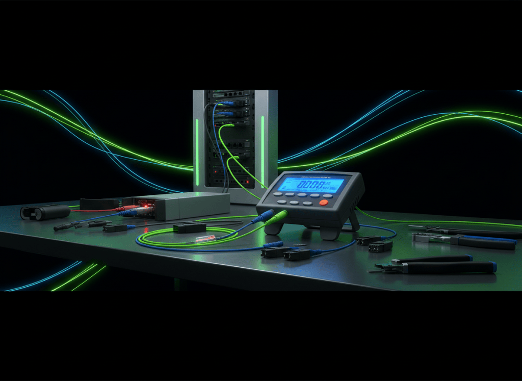
An optical power meter measures the amount of light arriving at a point in a fiber-optic system. Correct use requires more than connecting a patch cord and reading a number: wavelength, units, connector cleanliness, reference cords, calibration state, source stability, and receiver specifications all determine whether the measurement is meaningful.
OSFOTC.002 continues the Open Source Fiber Optics Technician Certification track from OSFOTC.001: Fiber Optic Safety, Handling, Inspection, and Cleaning Basics. The earlier lesson established safe handling, connector inspection, cleaning, bend-radius discipline, and source awareness. Those practices become measurement prerequisites here.
The engineering-level companion track begins with OSFOEC.001: Optical Link Budget Engineering — dB, Power Budget, Loss Budget, and Design Margin. The technician task is to obtain trustworthy measurements that engineering calculations can rely on.
The optical power measurement workflow
identify the circuit → confirm source state and wavelength → inspect and clean connectors → select the correct meter adapter → set the meter wavelength → select dBm for absolute power → connect the known-good reference path or system fiber → allow the source to stabilize → record the measured value → compare with transmitter or receiver specifications → document the test conditions
What an optical power meter measures
An optical power meter converts incoming light into an electrical signal and displays the measured optical power. The result may be displayed in watts, milliwatts, microwatts, or more commonly dBm.
The Fiber Optic Association describes optical power measurement as one of the fundamental tests in fiber systems. The meter must be configured for the wavelength of the source being measured and for a range appropriate to the expected signal. See FOA Fiber U — Optical Power Testing Quick Start.
Absolute power and dBm
dBm is an absolute optical power unit referenced to 1 milliwatt.
dBm = 10 log10(P / 1 mW)
Several reference points are useful:
- 1 mW = 0 dBm
- 0.1 mW = −10 dBm
- 0.01 mW = −20 dBm
- 0.001 mW = −30 dBm
- 10 mW = +10 dBm
A more negative dBm reading represents lower optical power. For example, −18 dBm is lower power than −8 dBm.
Corning’s fiber-optic system-testing tutorial likewise describes dBm as an absolute power measurement and dB as a ratio between two power levels. See Corning — Fiber Optic System Testing Tutorial.
Testing optical power
dBm and dB are not interchangeable
dBm represents an absolute optical power level. dB represents a difference or ratio between two power levels.
If a source produces −3 dBm and the far end of a link measures −7 dBm, the link has approximately 4 dB of loss:
loss = source power − receive power
loss = −3 dBm − (−7 dBm) = 4 dB
The FOA reference on dB and dBm distinguishes these units explicitly: power is measured in dBm, while loss is measured in dB.
This distinction is essential when documenting test results. Writing “−12 dB receive power” is not equivalent to “−12 dBm receive power.”
Wavelength selection
Optical detectors respond differently at different wavelengths. A power meter must therefore be set to the wavelength being measured so its calibration correction is appropriate.
- Multimode systems commonly use 850 nm and sometimes 1300 nm.
- Singlemode systems commonly use 1310 nm and 1550 nm.
- PON systems may also use wavelengths such as 1490 nm or 1577 nm depending on the technology.
- Specialized systems can use other wavelengths and must be tested according to the system documentation.
FOA’s quick-start testing procedure requires the meter wavelength to match the source wavelength. Measuring a 1310 nm source while the meter is configured for 850 nm can produce an incorrect result even if the connector and meter are otherwise functioning properly.
Connector cleanliness is part of the measurement
A contaminated ferrule can add loss before the signal reaches the detector. The meter may then report the contamination rather than the actual source or system condition.
The correct preparation remains the same as in OSFOTC.001:
- inspect the connector with approved equipment where required;
- clean using the approved method;
- inspect again;
- connect only when the endface is acceptable;
- keep reference cords and meter adapters clean throughout the test.
FOA Standard FOA-3 specifically includes cleaning connectors and mating adapters before measuring optical power.
Known-good reference cords
A reference cord provides a controlled optical connection between a source and a meter or between test equipment and the cable plant. A damaged or dirty reference cord can corrupt every measurement made with it.
- The fiber type must match the system being tested.
- The connector type must match the source, adapter, and meter interface.
- The cord should be inspected and cleaned before use.
- The cord should be known-good and periodically verified.
- Excessive bends or strain should be avoided during testing.
Reference cords should be treated as precision test accessories, not ordinary patch cords borrowed from an unknown rack.
Source stabilization
Optical sources can change output as they warm up. Test equipment instructions may specify a stabilization interval before measurements are taken.
A measurement taken immediately after turning on a source may not match a measurement taken after the source reaches stable operating temperature. Repeatability improves when the same warm-up and setup procedure is followed each time.
Five cable-plant testing approaches
Measuring transmitter output
Transmitter output power is measured by connecting the transmitter to the optical power meter through an appropriate known-good reference cable or test interface.
The process includes confirming the transmitter wavelength, cleaning the connection, setting the meter to the matching wavelength, allowing the source to stabilize, and recording the dBm value.
The result should be compared with the transmitter’s specified output range rather than with a generic expectation. Different optic classes and technologies can have significantly different launch-power limits.
Measuring receive power
Receive power can be measured at the far end of a live optical path by disconnecting the fiber from the receiver and attaching the fiber to the optical power meter, when the site procedure permits the circuit to be interrupted.
The measured receive power must be compared with the receiver’s operating window:
- Above the maximum receive level: the receiver may overload or saturate.
- Inside the specified receive range: optical power is acceptable, subject to other link conditions.
- Below receiver sensitivity: the receiver may experience errors or lose the link entirely.
The correct limits come from the actual transceiver or system specification. Generic values should not be substituted for the manufacturer’s data.
Power margin
A link can be operational while still having poor optical margin. If the measured receive power is only slightly above the receiver sensitivity threshold, normal aging, contamination, temperature change, an added patch connection, or a small bend loss can remove the remaining margin.
A simple receive margin can be expressed as:
receive margin = measured receive power − minimum acceptable receiver power
If measured receive power is −12 dBm and receiver sensitivity is −16 dBm, the simplified margin is 4 dB.
This operational measurement connects directly to the engineering concepts in OSFOEC.001, where the entire optical power budget and design margin are calculated before installation.
Insertion loss
Insertion loss testing compares a reference power level with the power measured after light passes through the cable plant. The difference is reported in dB.
The existing lesson on fiber-optic insertion loss introduces this concept. In technician practice, a light source and power meter are commonly used together to verify installed link loss against an allowable loss budget.
Insertion loss testing with a light source and power meter
Reference level versus absolute receive power
Two common measurement tasks use the same meter differently.
- Absolute power measurement: the meter displays the actual optical power at the measurement point in dBm.
- Relative loss measurement: a reference level is established, then the meter compares a later reading with that reference and reports the difference in dB.
Confusing these modes is a common technician error. A meter set to relative dB mode can produce a perfectly stable number that is not an absolute receive-power value.
Calibration and traceability
Power-meter accuracy depends on calibration. FOA guidance recommends calibration at manufacturer-specified intervals. Calibration compares the instrument against a known reference so measurements remain traceable within stated uncertainty.
A meter that powers on and produces readings is not automatically within calibration. Production test programs should track:
- instrument serial number;
- last calibration date;
- calibration due date;
- approved wavelength range;
- measurement range;
- adapter condition;
- reference-cord condition.
Measurement uncertainty
No optical measurement is exact. Uncertainty can come from the power meter, source stability, connector repeatability, reference-cord condition, wavelength mismatch, detector calibration, multimode launch conditions, and technician technique.
Consistency reduces uncertainty. The same test method, clean connectors, correct wavelength, stable source, verified reference cord, calibrated instrument, and documented setup produce results that can be compared over time.
Power-meter troubleshooting sequence
- Confirm the correct circuit and measurement point.
- Confirm the expected source wavelength.
- Confirm the meter is set to that wavelength.
- Confirm the display mode is dBm for absolute power.
- Inspect and clean all connector interfaces.
- Verify the reference cord and adapter.
- Confirm the transmitter or test source is active and stable.
- Repeat the measurement without changing unnecessary variables.
- Compare the result with the actual transmitter or receiver specification.
- Document the test setup and reading before moving to a different tool.
Common technician errors
- using dB mode when absolute dBm power is required;
- testing at the wrong wavelength setting;
- measuring through a dirty reference connector;
- assuming a dust-capped connector is clean;
- using an unknown patch cord as a reference cord;
- comparing measured power with a generic threshold instead of the actual optic specification;
- forgetting that a more negative dBm value means lower power;
- moving between 850 nm, 1310 nm, and 1550 nm tests without changing the meter setting;
- accepting a reading from an instrument with expired calibration;
- recording the number but not the wavelength, instrument, port, or circuit identity.
Field documentation
FOA Standard FOA-3 recommends documenting the test date, operator, test equipment, cable/fiber identification, wavelength, and measured power. A useful field record also includes:
- site and rack;
- patch panel and port;
- near-end and far-end circuit identity;
- transceiver type;
- meter model and serial number;
- reference-cord identifier;
- measured dBm value;
- expected specification range;
- pass/fail or escalation result;
- notes on cleaning or corrective action.
Exercises
- Convert the following reference points conceptually: identify whether −5 dBm, −15 dBm, or −25 dBm represents the highest optical power.
- A transmitter measures −2 dBm and the far end measures −6.5 dBm. Calculate the approximate link loss in dB.
- A receiver operates from −3 dBm to −18 dBm. Determine whether a measured receive level of −14 dBm is inside the stated operating range.
- Explain why a meter configured for 850 nm should not be used unchanged to measure a 1310 nm source.
- List the preparation steps required before connecting a production fiber to a power meter.
- Explain the difference between an absolute dBm measurement and a relative dB loss measurement.
- Create a field test record containing circuit ID, wavelength, meter serial number, measured power, and specification range.
- Describe how a dirty reference cord can cause a false troubleshooting conclusion.
Knowledge check
What does dBm represent?
An absolute optical power level referenced to 1 milliwatt.
What does dB represent in fiber testing?
A relative difference or ratio between two optical power levels, commonly used to express loss.
Which is higher optical power: −8 dBm or −18 dBm?
−8 dBm.
Why must the meter wavelength match the source wavelength?
Because detector response and instrument calibration vary with wavelength.
Why is a known-good reference cord important?
Because an unknown or damaged reference cord can add loss and corrupt the measurement.
What determines whether receive power is acceptable?
The specified operating range of the actual receiver or transceiver being tested.
What should be recorded with a measured power value?
At minimum, circuit identity, wavelength, test equipment, and the measured dBm result; production documentation should also include the applicable specification and test conditions.
Why can a functioning link still have a power problem?
Because it may operate with insufficient margin or excessive receive power even before a complete loss of link occurs.
Key takeaway
Optical power measurement is a controlled comparison between the actual light at a measurement point and the expected operating range of the system. Reliable results require the correct wavelength, clean interfaces, known-good reference cords, calibrated instruments, the correct dBm or dB mode, stable sources, and complete documentation. The number on the screen is only useful when the test conditions that produced it are known.
Safety note: This lesson is general technical education. It does not authorize interruption of production circuits or exposure to active optical sources. Follow site procedures, equipment labels, employer safety requirements, and manufacturer instructions.
Display note: this lesson uses standard Gutenberg paragraphs, headings, lists, and media embeds only. No decorative text-box or callout-box layout is used.
BitcoinVersus.Tech
Advertisement
Editor’s Note:
We volunteer daily to ensure the credibility of the information on this platform is Verifiably True. If you would like to support our research initiatives, please donate here: 3C9o19EH5HSiwEPyCTmEKzxhNCbo2X6TTb
BitcoinVersus.tech is not a financial advisor. This media platform reports on financial subjects purely for informational purposes.


Leave a Reply