dBm (decibel-milliwatt), also written dBmW, is a logarithmic unit of absolute power level referenced to 1 milliwatt (mW). In fiber optics, dBm is used to describe the optical power supplied by a transmitter or detected by a receiver. The measurement indicates light power at a specified test point; it does not independently describe data rate, signal quality or link reliability.
A decibel (dB) expresses a ratio of two power levels. In contrast, dBm fixes the reference at 1 mW. A reading of 0 dBm equals 1 mW, while −10 dBm equals 0.1 mW. Negative values denote power below the 1 mW reference, not physically negative optical power. The Fiber Optic Association (FOA) explains the distinction for optical-network measurements.
Definition and conversion formulas
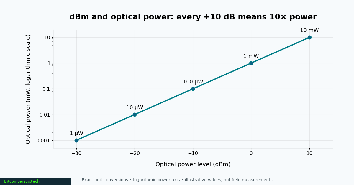
The decibel-milliwatt definition is P(dBm) = 10 log10[P / (1 mW)], with P expressed in the same physical power units as the reference. The inverse expression is P(mW) = 10P(dBm)/10. Both relationships describe logarithmic power units, not a logarithmic change in voltage or optical wavelength.
Every +10 dB in absolute level means 10 times as much power; +3 dB is approximately double, while −3 dB is approximately half. A zero-dBm value is a reference point rather than an absence of light. Values and computations below are exact unit conversions apart from displayed rounding.
| Optical level | Equivalent power |
|---|---|
| +10 dBm | 10 mW |
| +3 dBm | 1.995 mW |
| 0 dBm | 1 mW |
| −3 dBm | 0.501 mW |
| −10 dBm | 0.1 mW |
| −20 dBm | 0.01 mW (10 µW) |
| −30 dBm | 0.001 mW (1 µW) |
How dBm is measured in a fiber link
An optical power meter detects incoming light and reports an absolute value in dBm. The technician selects the appropriate calibration wavelength, often 850, 1310 or 1550 nanometers depending on the system and instrument. Optical measurements can be affected by connector cleanliness, coupling, calibration and test setup. The earlier optical power meter lesson covers reference settings and receiver-power checks.
An optical loss test set measures insertion loss relative to a launch reference. The loss is reported in dB, rather than dBm. An optical time-domain reflectometer (OTDR) analyzes returned light to estimate distance-dependent attenuation and identify reflective or lossy events; consult the bidirectional OTDR guide for limitations of event interpretation.
FlukeNetworksVideo, “Basic Testing with the MultiFiber™ Pro by Fluke Networks” (November 1, 2018). Manufacturer demonstration of fiber power-meter reference and measurement workflow; not a measurement of the example link.
Calculating optical loss and power budget
Consider a link whose optical transmitter provides −3 dBm and whose measured receiver input is −15 dBm. Under comparable operating and test conditions, the difference is 12 dB of end-to-end loss: −3 − (−15) = 12 dB. The subtraction produces dB, not dBm. Fiber attenuation is commonly specified in dB/km, and splice, connector and splitter losses contribute to the overall link loss.
Suppose a hypothetical receiver needs at least −18 dBm and the transmitter delivers −3 dBm. The nominal available power budget is 15 dB. A measured 12 dB path loss leaves 3 dB of remaining margin. Actual deployment also requires checking the manufacturer’s maximum receiver input, operating wavelength, modulation format, bit-error requirements and engineering allowances. The optical link-budget engineering reference expands the design method, while the FOA’s loss-budget guidance explains aging and degradation allowances.
Practical meaning and limitations
The same power reading cannot guarantee the same communication performance across different receivers. A transceiver’s permitted receive range depends on device design, wavelength and standard. The SFP and QSFP transceiver guide explains how optical modules convert electrical data into transmitted light; newer 800G and 1.6T links have additional signal-integrity requirements beyond average optical power.
An unexpectedly low dBm reading can point to excessive loss, a disconnected path or a failing source, but diagnosis requires more than one number. Inspect and clean fiber end faces safely, verify the test wavelength and reference conditions, and compare observations with the transceiver’s published operating limits. Never look directly into a fiber end face: optical transmitters may emit invisible laser light.
References and related reading
Primary technical references: FOA, Measuring Power in dB and dBm; FOA, Fiber Optic Testing FAQ; FOA, Calculating Fiber Optic Loss Budgets; and Fluke Networks, Fiber Testing Guide. For general mathematical background, see decibel and optical fiber.
BitcoinVersus.Tech Editor’s Note
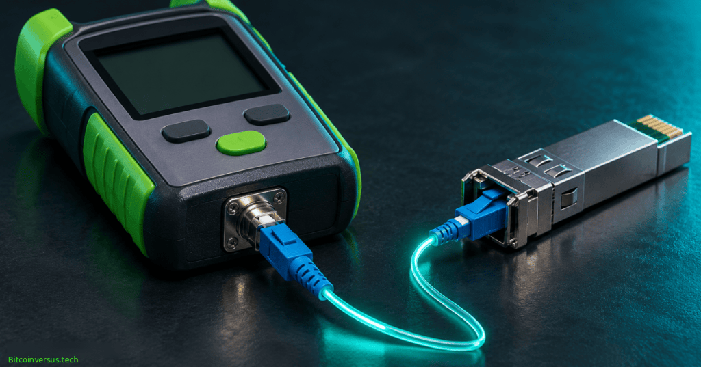
Encyclopedia reference reviewed November 8, 2026. Conversions follow the 1 mW definition and manufacturer-independent optical testing principles. The 12 dB loss and 15 dB power-budget examples are hypothetical and do not represent measured equipment. The featured image is a conceptual illustration. The linked Fluke Networks video provides instructional background; playback and device performance are separate questions.
We volunteer daily to ensure the information on this platform is Verifiably True. If you would like to support the research, please scan QR code.

Support independent reporting with an optional donation of 5,000 satoshis. Scan the original QR using a Bitcoin wallet and verify the destination 3C9o19EH5HSiwEPyCTmEKzxhNCbo2X6TTb and amount before sending.
BitcoinVersus.Tech is not a financial advisor. Financial coverage is provided purely for informational purposes.


Leave a Reply