
An optical transceiver is a hardware module that converts electrical data into an optical signal for transmission through fiber and converts received light back into electrical data. The same small component connects an Ethernet switch, router, server network card, storage device or optical transport platform to a fiber network. It is the replaceable meeting point of electronics, lasers, photodetectors, fiber connectors and communications standards.
This evergreen technical reference explains the entire subject from first principles: how a pluggable optical module works, what SFP, SFP+, SFP28, QSFP, QSFP-DD and OSFP actually mean, why wavelengths and fiber types matter, how an optical power budget is calculated, and how technicians diagnose links that fail or intermittently drop. It also covers modern 400G, 800G and coherent optics without treating every new module as interchangeable.
Definition and purpose
The term transceiver combines transmitter and receiver. In an optical network, the transmitting portion drives a light-emitting component—typically a laser—using an electrical signal from the host. The receiving portion uses a photodiode and associated electronics to recover information from light arriving through fiber. The host may be a network interface card, top-of-rack switch, metro router or dedicated optical line system.
Many Ethernet optical modules are hot-pluggable when the particular host and module permit it. They occupy a standardized mechanical cage, present an electrical interface to the switch or server, and expose one or more fiber connectors at the front. A transceiver is not the fiber itself and is not necessarily a complete protocol endpoint: a physical link still depends on supported electrical lanes, encoding, error correction, port configuration and the remote device.
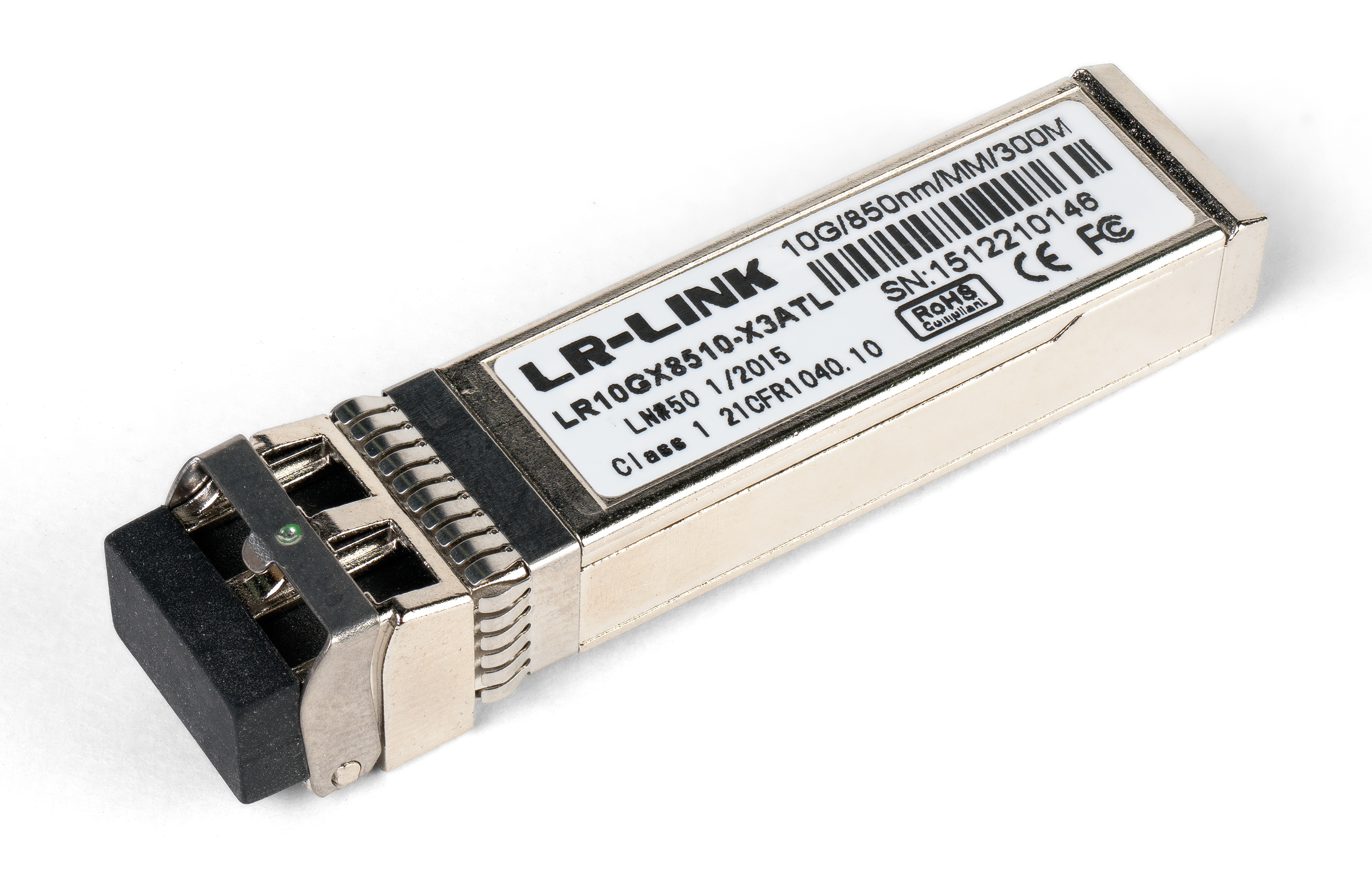
A module’s external appearance cannot establish its speed, wavelength, reach or connector polarity. Engineers read its label, electronic identification information, current datasheet and compatibility matrix. The term “SFP” also describes a physical module family rather than a guarantee that a particular optical interface operates at exactly one data rate.
Video: FS — SFP Optical Transceiver Overall Introduction (2019). Manufacturer training overview of SFP applications and variations; technical details must still be verified against the specific module datasheet.
The FS demonstration shows the practical idea of a compact pluggable module and highlights different reach and wavelength choices. From this point onward, the key distinction is between module form factor (what fits in the host) and optical/electrical interface (what it actually transmits).
Inside an optical transceiver
The optical transmit path begins with electrical data presented to a module’s host interface. Driver or digital signal processing circuitry controls the optical source, and the light is coupled to the front connector or attached cable. The received path collects light at a photodiode, uses amplification and decision or digital signal processing circuits, and returns data electrically to the host. High-speed modules can integrate clock/data recovery, equalization, gearboxes and forward-error-correction-related functions depending on architecture.
An optical module also contains non-data functions: identification memory; module-management interfaces; laser power and temperature control; supply-voltage monitoring; fault and alarm flags; and mechanical features that transfer heat to the cage. Some higher-capacity optics use multiple laser wavelengths or multiple fiber lanes inside a single module.
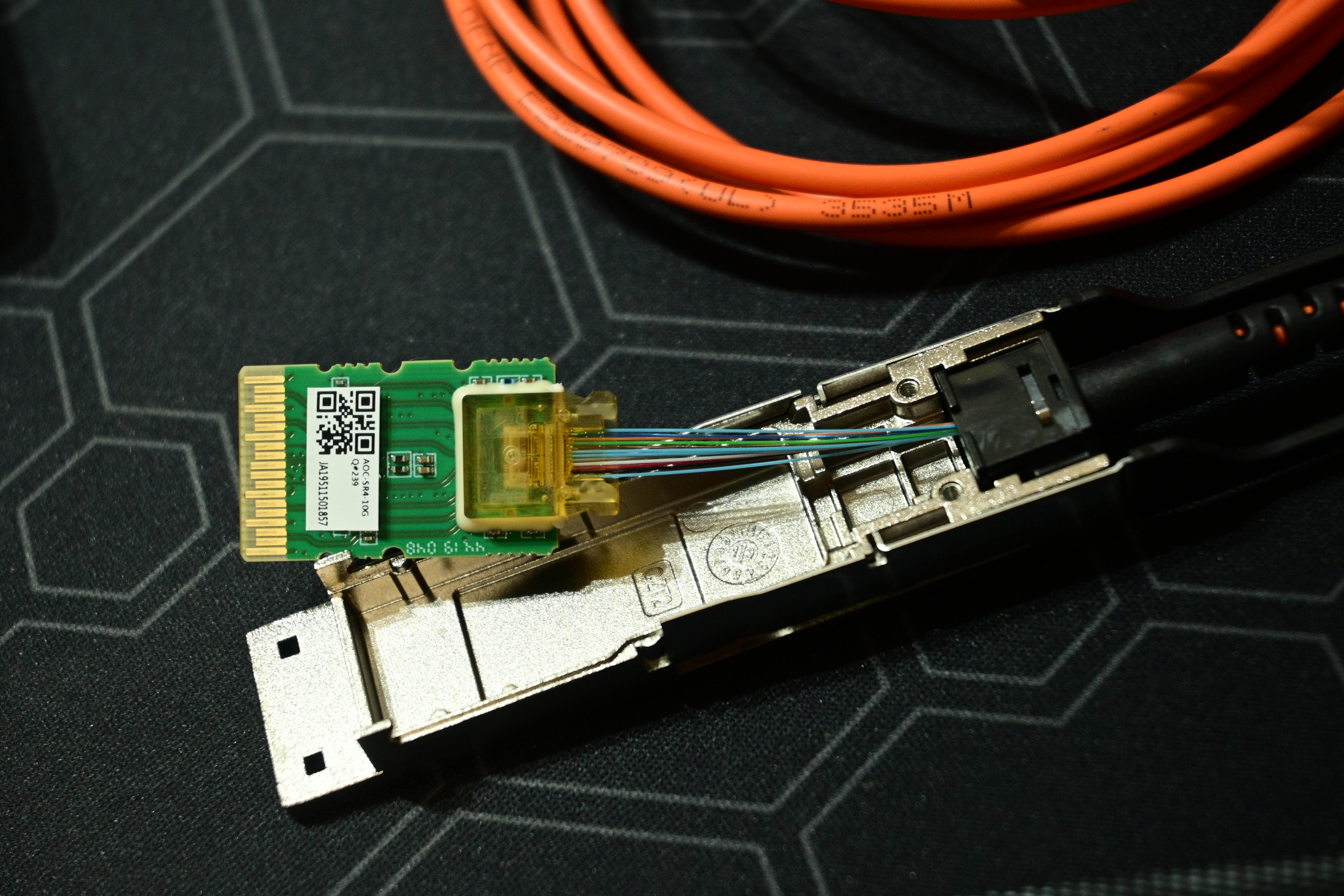
The disassembled module makes the manufacturing challenge visible: optical alignment, electrical contact integrity, electromagnetic shielding, heat extraction and consistent factory calibration all have to fit into a small hot-pluggable assembly. It is not a recommended field disassembly procedure—opening an optical module is usually destructive or warranty-voiding.
Major pluggable form factors
A form factor specifies the module’s mechanical envelope and host-facing interface family. Speed labels and reach markings are separate. In particular, an SFP cage does not automatically support SFP+ signaling, an OSFP module will not mechanically fit a QSFP-DD cage, and a higher-speed QSFP-DD host’s backward compatibility depends on its electrical design and supported software.
| Module family | Common Ethernet usage | Typical host or role |
|---|---|---|
| SFP | 100 Mb/s or 1 Gb/s variants | Enterprise access, management and legacy networks |
| SFP+ | 10 Gb/s | Server, switch and storage uplinks |
| SFP28 | 25 Gb/s | High-density server and access connections |
| QSFP+ | 40 Gb/s | Four-lane legacy data-center connections |
| QSFP28 | 100 Gb/s | Data-center, enterprise core and transport ports |
| QSFP56 / QSFP-DD | 200G and 400G configurations; QSFP-DD families also support 800G | High-density data-center and AI network connections |
| OSFP | 400G and 800G configurations | Higher-power, high-density optical interfaces |
| XFP / CFP / CFP2 | Historical and specialized 10G/coherent transport use | Older switching and optical transport equipment |
High-speed modules may support breakout, in which a single physical port presents multiple lower-rate logical connections. Breakout is not automatic: the host must support the specific lane mapping, cable assembly, transceiver variant, firmware and forward error correction. For example, a supported 400G port may use 4 × 100G breakout, while a supported 800G port may expose 2 × 400G or 8 × 100G in a particular design. Do not assume a generic “800G optic” supports all such permutations.
Video: AddOn Networks — SFP vs. QSFP Transceivers: What Is the Difference? (2020). A separate technical overview comparing pluggable families, not a repeat of the preceding SFP introduction.
The comparison is useful for distinguishing port density and lane design from link capacity. In purchasing, “QSFP” alone is too broad a specification: the exact mechanical family, lane count, connector type, optical specification, supported host speed and thermal limits must all be checked.
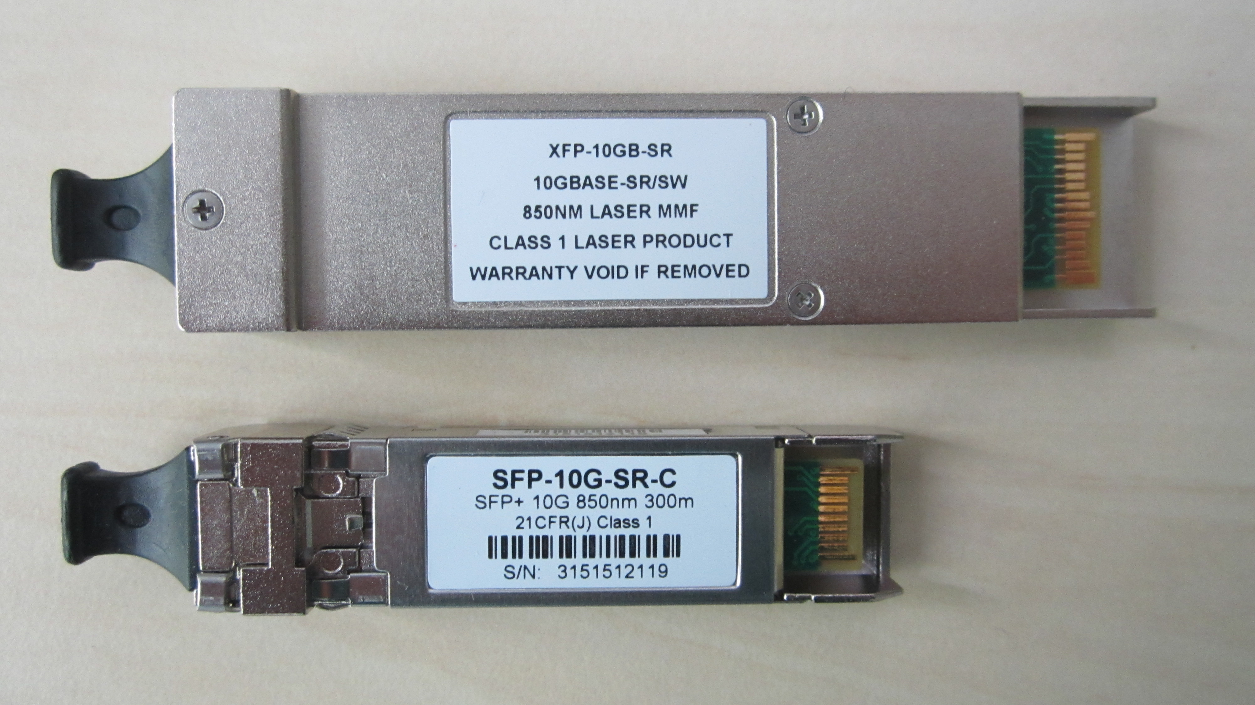
One reason the module ecosystem has grown complicated is that standards for the outer case, electrical host interface, optical signal and management memory often come from different industry groups. Multi-source agreements (MSAs), IEEE Ethernet specifications and the Optical Internetworking Forum (OIF) play complementary roles; a compliant optic can still be blocked or unsupported by a particular switch firmware release.
Fiber types and connector geometry
Single-mode fiber (SMF) supports one dominant spatial propagation mode and is commonly used for campus, metro, long-reach and many modern data-center applications. Multimode fiber (MMF) supports multiple modes, usually uses larger-core fiber and is common in shorter building or data-center links. The exact reach depends on transmitter type, fiber grade, wavelength, modulation, loss and dispersion—not simply whether the jacket is yellow or aqua.
The most recognizable fiber connector for duplex SFP-style optics is LC. Parallel optics commonly use MPO/MTP-style multifiber connectors, and some modules use a fixed cable assembly. LC/UPC and LC/APC connectors cannot be treated as interchangeable; a physical mismatch can damage end faces or cause excessive loss. Our separate fiber connector and polarity reference explains LC, SC, MPO, transmit/receive direction and end-face verification.
An active optical cable (AOC) integrates the optical modules and fiber into one factory-terminated assembly, whereas a direct attach copper (DAC) cable is an electrical connection. Both can occupy cages associated with optical transceivers, but DAC is not a fiber-optic transceiver. Connector and cable terms should not be confused with the Ethernet port speed.
Wavelengths and optical naming
Optical wavelengths are usually described in nanometers (nm). Approximately 850 nm is common for short-reach multimode optics; 1310 nm often appears in single-mode short and medium reach; and 1550 nm is a common window for longer-reach and wavelength-division-multiplexed systems. These are useful patterns, not universal compatibility rules.
Ethernet markings such as SR, LR and ER typically denote short-, long- and extended-reach physical interfaces within a specific speed family. But the same letters do not specify one identical distance across every standard. For example, Cisco documents 10GBASE-SR reaching up to 300 m on OM3 or 400 m on OM4, while its 10GBASE-LR SFP+ is specified for 10 km on compliant single-mode fiber. These are specific module and media specifications, not universal fiber-distance guarantees.
BiDi (bidirectional) optics usually send and receive on complementary wavelengths over one single-mode fiber. The paired end modules must have reciprocal transmit and receive assignments. CWDM and DWDM carry separate wavelength channels over shared fiber through multiplexing equipment. Coherent transceivers go further by encoding information in amplitude, phase and polarization using advanced receivers and digital signal processing; this is not the same architecture as an ordinary 10GBASE-SR SFP+.
The DWDM channel-planning reference covers frequency grids and spacing, while our coherent transmission lesson explains I/Q modulation, DSP, OSNR and forward error correction in detail.
Signaling: NRZ, PAM4, optical lanes and error correction
An optical link carries symbols, not an abstract internet throughput number. Traditional NRZ signaling uses two levels per symbol; PAM4 uses four levels, carrying two bits per symbol before coding and overhead. Faster serial lanes and additional optical wavelengths or fibers let equipment increase aggregate bandwidth. Forward error correction (FEC) may be required to meet an acceptable post-FEC bit-error rate, especially for high-speed PAM4 links.
A module’s marketed “100G” or “800G” rate describes a supported Ethernet service class, not an assurance that all host-facing and optical lanes use the same count or signaling scheme. Some modules use electrical-to-optical gearboxing, multiple parallel fibers or multiplexed wavelengths; coherent optics use still more advanced architectures. Actual payload throughput and line signaling rates also differ because of coding, protocol overhead and FEC.
Link budgets: transmit power, loss and receiver limits
Engineers use an optical link budget to determine whether enough light will reach the receiver without exceeding its maximum input. Transmit power and received power are often stated in dBm, an absolute power unit referenced to 1 milliwatt; loss is measured in dB, a ratio. The basic accounting relationship for a simple optical path is Expected Rx (dBm) = Tx (dBm) − total path loss (dB). This is a planning approximation, not a substitute for specification limits, dispersion or measured compliance.
Consider an illustrative link with +0 dBm transmitter output, 6 dB of fiber and connector loss, and an additional 1 dB of engineering allowance. At the receiver the estimated level is −7 dBm. If its applicable specified minimum input is −12 dBm, the approximate remaining margin is 5 dB. The engineer must also verify the maximum permitted receiver level: too much optical power can overload a receiver even when the transceiver and fiber type otherwise match.
| Planning input | Illustrative value | Interpretation |
|---|---|---|
| Optical transmit power | +0 dBm | Assumed module output for the example, not a universal rating |
| Fiber, connector and splice loss | 6 dB | Combined estimated end-to-end attenuation |
| Engineering allowance | 1 dB | Extra allowance for uncertainty and future degradation |
| Expected received level | −7 dBm | 0 − 6 − 1 |
| Hypothetical receiver minimum | −12 dBm | Representative required power for this example only |
| Estimated reserve | 5 dB | −7 dBm minus (−12 dBm); still check overload and other impairments |
For high-speed Ethernet, the optical modulation amplitude (OMA), dispersion penalty, transmitter eye characteristics, FEC, symbol error performance and connector reflections may matter in addition to average receive power. For a coherent DWDM span, optical signal-to-noise ratio and nonlinear impairments are central. Our link-testing and certification lesson discusses the measurement distinction between link attenuation and optical transmission quality.
Digital diagnostics and module management
Many pluggable optics expose digital optical monitoring (DOM) or digital diagnostic monitoring (DDM) values. Depending on the transceiver and host, these may include module temperature, supply voltage, transmitter bias current, average transmitted optical power, received optical power and upper/lower warning thresholds. A missing DOM reading does not automatically mean no light is present; some modules or platforms simply do not expose that parameter.
Host interfaces vary. Cisco switches commonly use variants of show interfaces transceiver detail, while Junos platforms use show interfaces diagnostics optics <interface-name> where supported. On high-speed QSFP-DD and OSFP devices, modern module-management implementations may follow OIF’s Common Management Interface Specification (CMIS). OIF lists CMIS revision 5.4 from May 2026 among its published agreements. Read platform manuals and permissions before issuing commands.
When investigating low receive power, a DOM value should be correlated with the remote transmitter’s reading, fiber path, patch records and a calibrated optical power meter. A single low value is not proof that the near-end transceiver failed. DOM is useful trend and alarm evidence, but it does not replace connector inspection, insertion-loss measurements or an appropriately selected OTDR test. See our optical performance-monitoring lesson for deeper telemetry interpretation.
Compatibility: what must match on both ends
- Host cage and pin interface: SFP, SFP+, QSFP28, QSFP-DD or OSFP must be supported by the port and its electrical design.
- Speed and lane configuration: both endpoints must agree on an actual supported Ethernet physical interface and breakout mode.
- Optical medium: the same compatible single-mode or multimode fiber type, connector and polarity must be used.
- Wavelengths: duplex optics generally require a compatible transmit/receive wavelength; BiDi pairs require complementary wavelengths.
- Reach and power: the transmitter range, receiver sensitivity/overload limits, attenuation, dispersion and any required attenuation must fit the link.
- FEC and signaling: both endpoints must use interoperable optical interfaces and supported FEC modes.
- Software qualification: vendor coding, permitted module identity, approved firmware and switch port configuration must match.
- Thermals and electricity: module power consumption, cage airflow, heat-sink design and supported temperature range must be within the host’s limits.
An inexpensive third-party optic may perform perfectly in a qualified host, but “MSA-compliant” does not by itself confirm acceptance by all switch operating systems. Vendor compatibility matrices, transceiver software state and operating-temperature limits are relevant. Refer to Cisco’s current transceiver technical documents or the equivalent manufacturer documentation before purchasing production optics.
Troubleshooting an optical transceiver safely
The following is a diagnostic order for trained network technicians. It emphasizes observation, non-destructive checks and safety. Do not defeat laser protections, look into fiber ends, touch exposed optics or perform unapproved live fiber disconnects.
- Confirm the symptom: distinguish an interface that never links, a port that intermittently flaps, elevated CRC/FEC errors and a link that passes optical checks but has a network configuration fault.
- Capture the baseline: record local/remote device, port, module identity, software version, speed, error counters, link-state transitions, module temperature and available DOM readings.
- Verify compatibility: compare both module part numbers, connector geometry, fiber grade, wavelengths and any required FEC or breakout settings.
- Inspect and clean fiber: use a proper inspection microscope and approved cleaning materials, following the inspect–clean–inspect discipline. Never blindly clean an end face that already passes inspection.
- Examine optical levels: compare measured or monitored Tx/Rx values with the exact module’s power specifications; check both low-power margin and overload risk.
- Check the physical route: patch-panel records, fiber polarity, connector damage, bend radius, suspected splice loss and shared optical equipment matter.
- Test with known-good equipment: swap one element at a time under approved change control, maintaining matched optical specifications and a recorded baseline.
- Verify stability: confirm link, DOM trend, corrected/uncorrectable FEC counters, errors, temperature, operational throughput and any optical power measurements after remediation.
Fluke Networks recommends inspection before mating every fiber end face, cleaning when needed and inspecting again after cleaning. An MPO connector has multiple end faces, any of which may affect a parallel optical link. For details, read Fluke’s inspection and contamination guidance and our IEC end-face inspection lesson.
Practical deployment examples
A 10G switch uplink across a building
Two network closets need a 10 Gb/s connection. One closet has a 10G SFP+ port; the far end also supports 10G. The technician verifies whether the existing path is OM3/OM4 multimode or single-mode. If it is OM3 over a compliant short route, a supported 10GBASE-SR pair may work; if the route is G.652 single-mode across several kilometers, compatible 10GBASE-LR optics are a more suitable starting point. The team verifies loss and compatibility rather than choosing by distance alone.
A fiber-connected storage or AI server rack
A storage cluster or high-speed server fabric is being upgraded from 25G to 100G ports. The presence of an SFP28 module in the old server does not make it a 100G optic. The new port may require QSFP28 or another approved 100G form factor and a matching switch port. A successful design also checks host lanes, transceiver power, supported breakout modes, fiber plant, FEC and the target NIC’s interface capabilities.
A 400G or 800G data-center interconnect
A large data center needs high-density optical connectivity. For an intra-building link, parallel multimode or single-mode 400G/800G optics may be applicable depending on the installed fiber and required reach. For metro connectivity, dense wavelength-division multiplexing and coherent ZR/ZR+ pluggables can be appropriate. Cisco’s July 2026 800G coherent data sheet describes 800ZR over amplified DWDM links up to 120 km and ZR+ links over 1,000 km under its specified system conditions; these are product capabilities with engineered optical paths, not blanket distance guarantees for all 800G modules.
Power and cooling become significant at high densities: multiplying module watts by dozens of switch ports creates substantial chassis heat load. The physical cage, platform airflow direction and module qualification should be included in network capacity planning. See our coverage of a field test of 800G over an existing fiber route for a real deployment context.
A short glossary
- ASIC: Application-specific integrated circuit; networking ASICs handle packet forwarding or data-plane functions.
- BiDi: Bidirectional optical module pairing different transmit and receive wavelengths on one fiber.
- Breakout: A supported mapping from one physical high-speed port to multiple lower-rate interfaces.
- CWDM / DWDM: Coarse and dense wavelength division multiplexing, placing multiple optical channels on fiber.
- DDM / DOM: Digital diagnostic/optical monitoring data supplied by modules and their hosts.
- dB / dBm: Relative power ratio / absolute optical power referenced to 1 mW.
- FEC: Forward error correction used to recover transmitted data despite a supported level of errors.
- LC: A compact fiber-optic connector frequently used for duplex SFP-style modules.
- Loss budget: Available margin between transmitter power, path attenuation and acceptable receiver level.
- MPO: Multi-fiber push-on connector used in numerous parallel optical systems.
- NRZ / PAM4: Two-level / four-level electrical or optical signaling formats.
- OSNR: Optical signal-to-noise ratio, especially important for amplified and coherent optical transport.
- QSFP-DD: Quad small form-factor pluggable double-density module family.
- Receiver overload: Excess input optical power beyond a receiver’s specified acceptable range.
- SMF / MMF: Single-mode / multimode optical fiber.
- Tx / Rx: Transmit and receive directions of a link.
Frequently asked questions
Is an SFP the same thing as a fiber-optic cable?
No. The SFP is the pluggable electronics that transmits or receives light; the fiber is the transmission medium connected to it. Some active optical cable assemblies integrate modules and the cable into one item.
Will a 10G SFP+ optic work in any SFP port?
No. A physical fit does not establish electrical signaling compatibility or software support. Verify both the physical host specification and the supported 10G optics list for the exact device.
Can two long-reach optics communicate over a short patch cord?
Sometimes, but not by assumption. Certain powerful long-reach optics require a suitable fixed attenuator on short links to avoid receiver overload. Follow the specific manufacturer’s power limits and attenuator requirements.
Does a good DOM receive-power reading prove a fiber link is healthy?
No. A link can have optical power yet still suffer contamination, reflection, intermittent defects, incompatible FEC, incorrect speed configuration or elevated symbol errors. Use appropriate optical and Ethernet-level tests.
What is the biggest difference between ordinary SFP optics and 800G coherent modules?
Ordinary SFP optics typically implement relatively simple intensity-based short- or medium-reach links. 800G coherent modules employ advanced modulation, coherent detection and digital processing to operate over engineered wavelength-division-multiplexed optical networks. The form factor alone never defines that internal architecture.
Primary specifications and further reading
The following documents support this evergreen guide: Cisco — 10GBASE SFP+ module data sheet (updated October 2026); Cisco — 800G OSFP module data sheet; Cisco — 800ZR/ZR+ coherent optics (July 2026); OIF — CMIS and other implementation agreements; Juniper — optical DOM CLI; Fluke Networks — inspection and cleaning; and Ethernet Alliance — Ethernet technology resources. Photo copyright attribution is provided directly beneath each in-story photograph.
Conclusion
The correct optical transceiver is the one that satisfies every layer of the connection: a supported host cage and signal, appropriate optical standard, fiber type, wavelength, connector polarity, path loss, receiver limits, error correction, management interface and thermal environment. Form-factor names are the beginning of selection, not its conclusion. A disciplined optical engineer checks the complete path and then verifies the result with real measurements.
Editor’s Note: We volunteer daily to ensure the credibility of the information on this platform is Verifiably True. If you would like to support our work and help further secure the integrity of our research initiatives, please scan the QR code below to donate 5,000 sats.

To scan from a phone, open this article on a laptop or larger screen and use a compatible Bitcoin wallet. Confirm the address before sending: 3C9o19EH5HSiwEPyCTmEKzxhNCbo2X6TTb.
BitcoinVersus.tech is not a financial advisor. This media platform reports on financial subjects purely for informational purposes.


Leave a Reply