Elementary Overview
Dense wavelength division multiplexing (DWDM) lets many independent optical channels share one strand of fiber by assigning each carrier a different optical frequency. Channel planning is the engineering job of deciding exactly where those carriers belong in the spectrum so they do not interfere with one another and still work with the selected transceivers, filters, link budget, and dispersion limits. This lesson focuses only on that frequency-plan problem.
The ITU-T Grid Defines the Channel Centers
ITU-T G.694.1 defines the DWDM frequency grid around an anchor of 193.1 THz. Common fixed-grid spacings include 100 GHz, 50 GHz, 25 GHz, and 12.5 GHz. A 50 GHz grid can be expressed as f = 193.1 THz + n × 0.05 THz, where n is an integer. The standard is fundamentally a frequency plan even though field labels often show approximate wavelength in nanometers. The relationship λ = c/f converts frequency to wavelength, which is why equal frequency spacing does not produce perfectly equal nanometer spacing across the band.
Fixed Grid and Flexible Grid Allocate Spectrum Differently
A fixed grid assigns carriers to regularly spaced center frequencies, which is convenient when channels have similar spectral width. The flexible grid keeps the same 193.1 THz reference but allows center-frequency granularity of 6.25 GHz and slot widths in 12.5 GHz increments. That flexibility matters when coherent carriers using different bit rates, baud rates, and modulation formats need different amounts of spectrum. A wider high-capacity signal can receive a wider slot without forcing every neighboring channel to consume the same amount of spectrum. The engineer still has to make sure slots do not overlap and that the signal format, transceiver, and line system support the planned allocation.
Mux/Demux Filters and Guard Bands Turn the Plan Into Hardware
A DWDM multiplexer combines wavelength-specific optical inputs onto one common fiber, while a demultiplexer separates the composite signal at the far end. Real optical filters have finite passbands and finite isolation, so channel edges cannot be treated as infinitely sharp. The design needs enough separation for filter roll-off, transmitter frequency tolerance, modulation bandwidth, and implementation margin. Unused spectrum between occupied slots can serve as a guard band. The mux/demux also adds insertion loss, so its loss belongs in the optical power budget.
Practical Planning Starts With Services and Ends With a Spectrum Map
Begin with the required services, line rates, reach, and expansion plan. Decide which services need dedicated wavelengths and whether the system uses a fixed or flexible grid. Assign each carrier a center frequency and required slot width, verify that no occupied slots overlap, then check the mux/demux or ROADM passbands and confirm every selected optical module supports the exact assignment. The final spectrum map should record channel identifier, center frequency, approximate wavelength, slot width, endpoints, route, expected optical power, and reserved spectrum. That record should stay with the link budget, dispersion analysis, and loss-test records.
Troubleshooting Separates Frequency Errors From Power and Fiber Errors
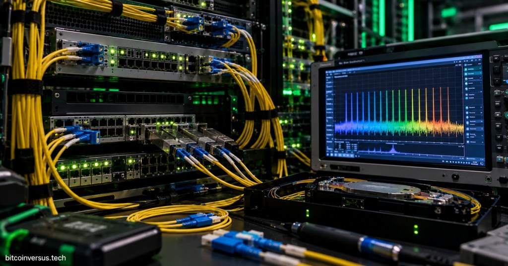
When a DWDM channel fails, first verify that the transmitter is tuned to the planned center frequency and connected to the matching wavelength port. Then use an optical spectrum analyzer when available to confirm that the carrier exists, sits inside the expected passband, and has adequate spacing from neighboring channels. A missing carrier can be a tuning, patching, transmitter, or filter-port problem; a weak carrier can instead point toward connector loss, mux insertion loss, attenuation, or amplification. If receive power is acceptable but BER remains poor, investigate signal quality, dispersion, FEC, OSNR, and spectral overlap rather than assuming the fiber is broken.
Worked Example
- Requirement: four 100G services over one fiber pair using a 50 GHz fixed grid.
- Reference: 193.1 THz.
- Channel 1: n = 0 gives 193.10 THz.
- Channel 2: n = 1 gives 193.15 THz.
- Channel 3: n = 2 gives 193.20 THz.
- Channel 4: n = 3 gives 193.25 THz.
- Verification: each transceiver, mux/demux port, and receiver must match the intended center frequency and support the planned spacing.
- Field note: approximate wavelengths may be recorded for identification, but the authoritative engineering plan remains frequency-based.
Engineering Checklist
- Confirm service count, data rates, reach, and growth requirements.
- Confirm single-mode fiber type and usable optical band.
- Select fixed-grid or flexible-grid architecture.
- Assign center frequencies from ITU-T G.694.1.
- Assign slot widths that match actual signal bandwidth.
- Verify mux/demux or ROADM passbands and insertion loss.
- Verify each transceiver supports its assigned frequency.
- Reserve enough spectrum for guard bands and expansion.
- Update the optical link budget with passive-device loss.
- Verify dispersion and high-speed signaling constraints.
- Document the spectrum map and physical port mapping.
- During turn-up, compare live spectrum measurements with the documented plan.
Exercises
- Using a 50 GHz grid anchored at 193.1 THz, calculate the center frequencies for n = −2, −1, 0, 1, and 2.
- Explain why the ITU-T grid is defined in frequency rather than approximate wavelength.
- Describe the difference between a fixed 50 GHz grid and a flexible-grid slot.
- Explain why mux/demux passband width matters even when transmitters have different center frequencies.
- List four reasons to reserve guard spectrum between occupied channels.
- Describe how an optical spectrum analyzer can distinguish a wavelength-assignment problem from a total-loss problem.
Knowledge Check + Answers
- What is the ITU-T DWDM anchor frequency? 193.1 THz.
- What are common fixed-grid spacings? 100 GHz, 50 GHz, 25 GHz, and 12.5 GHz.
- What is the flexible-grid center-frequency granularity? 6.25 GHz.
- What is the flexible-grid slot-width granularity? 12.5 GHz.
- What does a DWDM multiplexer do? It combines multiple wavelength channels onto one common fiber.
- Why use guard bands? To provide spectral separation for filter roll-off, transmitter tolerance, modulation bandwidth, and implementation margin.
- Does a correct wavelength plan guarantee a working link? No. Power, dispersion, signal quality, and interoperability must also pass.
Reference Resources
- ITU-T G.694.1 — DWDM Frequency Grid
- Cisco — Dense Wavelength Division Multiplexing
- Ciena — What Is WDM or DWDM?
- XKL — Introduction to DWDM Tutorial
- OSFOEC.003 — Optical Transceiver Selection Engineering
- OSFOEC.004 — High-Speed Optical Signaling
Elementary Conclusion
DWDM channel planning is the process of deciding exactly where each optical signal is allowed to live. The ITU-T grid supplies the map, fixed or flexible spacing determines how much spectrum each carrier receives, and mux/demux filters turn the plan into a physical optical path. The engineer then proves that the transceivers, power budget, dispersion, and signal quality all agree with that map. Assign frequencies deliberately, leave enough spectral room, document every channel, and verify the live spectrum against the plan.
BitcoinVersus.Tech
Build deeper networking, fiber-optic, semiconductor, data-center, firmware, and engineering skills through the free BitcoinVersus.Tech Open CERT lesson library.
Editor’s Note:
Support: BitcoinVersus.Tech is independently maintained to keep technical education open and accessible.
BitcoinVersus.tech is not a financial advisor. This media platform reports on financial subjects purely for informational purposes.


Leave a comment