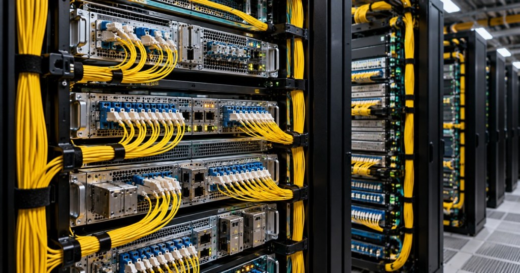
Optical Transport Network engineering is the digital structure that lets many different client services be wrapped, monitored, multiplexed, switched, protected, and transported across high-capacity optical systems. DWDM gives the network wavelengths. OTN gives engineers a standardized way to place services onto those wavelengths with framing, overhead, error monitoring, forward error correction, and deterministic Layer 1 transport.
This lesson follows OSFOEC.010: Optical Performance Monitoring and Telemetry. That lesson focused on measuring live optical health. OSFOEC.011 moves one layer into the transport structure itself: how client signals become OPU, ODU, and OTU signals, how lower-rate services are groomed into higher-rate transport containers, and how engineers use OTN overhead and switching to operate a network predictably.
Ciena’s OTN Chalk Talk gives a concise overview of the digital-wrapper concept, OTN hierarchy, and why OTN is used to carry multiple client technologies across optical networks.
Elementary Overview
The simplest way to think about OTN is as a standardized shipping system for digital traffic. Ethernet, Fibre Channel, legacy SONET/SDH, and other client signals are placed into defined transport containers. Those containers can be monitored and, depending on the platform, combined with other containers before being sent over a coherent optical wavelength.
ITU-T Recommendation G.709 defines the interface signals, hierarchy, overhead, frame structures, bit rates, and client mappings used by OTN. ITU-T lists the 2020 edition of G.709/Y.1331 together with in-force corrigenda and amendments, including Amendment 4 approved in July 2025. The architecture continues to evolve for newer rates and flexible transport while preserving the basic OTN idea: separate the client service from the line system through a managed transport layer.
Learning Objectives
- Explain the purpose of OTN and how it differs from the DWDM photonic layer.
- Describe the relationship among the client signal, OPU, ODU, and OTU.
- Explain why OTN is commonly described as a digital wrapper.
- Distinguish client mapping from ODU multiplexing and ODU switching.
- Explain the purpose of OTU, ODU, and OPU overhead.
- Describe how FEC improves transport margin and why FEC behavior depends on interface type.
- Explain ODU grooming and why it can improve wavelength utilization.
- Identify common OTN alarms and use them to narrow a fault domain.
- Relate OTN transport to coherent optics, ROADMs, protection, and telemetry.
- Build a basic engineering workflow for provisioning and verifying an OTN service.
OTN and DWDM Are Different Layers
DWDM combines multiple optical wavelengths onto the same fiber. Its main engineering concerns include wavelength assignment, channel spacing, launch power, amplifier gain, optical noise, filtering, and spectral routing. Review OSFOEC.005: DWDM Channel Planning for that layer.
OTN is primarily a digital transport framework. It defines how client traffic is framed and monitored before that traffic is carried over an optical channel. A transport system may therefore have an Ethernet client on the front panel, map that service into an OTN structure internally, then modulate the resulting line signal onto one wavelength that travels through the DWDM network.
A ROADM can route the wavelength through the optical layer without necessarily examining the OTN payload. An OTN switch, by contrast, operates in the digital transport layer and can terminate, groom, add, drop, or cross-connect ODU containers. That distinction is fundamental: a ROADM switches light paths; an OTN switch switches digital transport containers.
The OTN Hierarchy: Client to OPU to ODU to OTU
The standard hierarchy is easiest to understand from the inside outward.
- Client signal: the service being transported, such as Ethernet, Fibre Channel, or another supported signal.
- OPU — Optical Channel Payload Unit: carries the adapted client payload and the overhead needed to describe how that client was mapped.
- ODU — Optical Channel Data Unit: adds path-level transport overhead around the OPU. The ODU is the principal digital path container used for monitoring, multiplexing, grooming, and switching.
- OTU — Optical Channel Transport Unit: adds section-oriented transport overhead around the ODU and, for classic OTUk structures, a defined FEC area for transmission across an optical channel connection.
Cisco summarizes the same nesting relationship as client payload → OPU → ODU → OTU. The OPU supports client adaptation, the ODU supports path-level operational and maintenance functions, and the OTU supports transport across the optical connection. Thinking in nested containers is more useful than memorizing acronyms independently.
Why OTN Is Called a Digital Wrapper
The client service does not need to become IP or Ethernet simply because it is crossing the optical network. OTN can transparently wrap a supported client signal so the transport layer can monitor and carry it while preserving the client’s own structure. This makes OTN useful in carrier, data-center-interconnect, utility, storage, research, and private backbone networks that carry different service types.
The wrapper adds engineering information that the native client may not provide to the optical transport system: trace identifiers, parity/error monitoring, backward defect information, communication channels, protection coordination, payload identification, and mapping information. The exact fields depend on the OTN structure and interface.
The Classic OTUk Frame
ITU-T G.709 defines the classic OTUk digital frame as four rows by 4,080 columns. In that structure, 256 columns are allocated for forward error correction. The remaining portion carries frame alignment, OTU overhead, the ODU, and the client payload nested inside the OPU. Newer OTN structures such as OTUCn and some interface-specific formats do not use exactly the same FEC placement, so engineers should not assume that every modern coherent interface is simply a larger copy of OTU1 through OTU4.
The important principle is not the drawing dimensions alone. OTN separates payload from overhead in a repeatable structure so network elements can align frames, identify the transported service, monitor errors, exchange management information, and localize faults independently of the client protocol.
OPU Overhead: How the Client Fits
The OPU exists because client signals do not naturally have the exact same rate and timing as the OTN container. Mapping procedures adapt the client into the OPU payload while preserving enough information for the far end to reconstruct the service correctly. Depending on the client and OTN generation, mapping may use defined procedures such as GFP-based or generic mapping mechanisms.
For engineering work, the key questions are: What is the client signal? Which OPU/ODU container is valid for it? Which mapping method does the platform implement? Is the mapping transparent to client timing and overhead? And does the far end support the same mapping behavior?
ODU Overhead: The Path Layer
The ODU represents the managed digital path through the OTN network. Its overhead supports functions such as path monitoring, trace identification, error monitoring, backward defect indication, tandem connection monitoring, and general communication channels. Because the ODU is the switching and grooming object, engineers often think in ODU paths when designing multi-node OTN services.
Tandem Connection Monitoring is especially useful when one end-to-end service crosses multiple administrative or operational domains. A carrier can monitor a subsection of the ODU path without changing the client signal itself. That creates a way to determine which network segment is contributing errors when the service crosses several operators or transport domains.
OTU Overhead: The Transport Section
The OTU adds transport-section functions around the ODU. Typical OTU-level monitoring includes frame alignment, section monitoring, trace information, parity/error measurements, backward defect indication, and a general communication channel. A fault can therefore appear at OTU level even when the client service itself has not yet failed.
On operational equipment, OTU and ODU alarms should be interpreted separately. A trace mismatch, loss of OTN frame, ODU payload-type mismatch, high BER threshold, or backward defect indication each points toward a different part of the service path. Cisco platforms, for example, expose distinct G.709 OTU and ODU report controls and performance thresholds rather than treating OTN as a single up/down alarm.
Forward Error Correction
Forward Error Correction adds redundant information that allows the receiver to detect and correct a controlled number of transmission errors. This increases usable optical margin and can extend reach or reduce the number of regeneration points required for a target error rate.
Classic OTUk structures include a defined FEC area. Modern coherent interfaces may use more advanced interface-specific hard-decision or soft-decision FEC schemes, and the exact FEC can be tied to the modem, modulation, baud rate, and line specification. Therefore, “OTN uses FEC” is correct at a high level, but an engineer must still verify the actual FEC mode negotiated or provisioned on the specific platform.
FEC also produces valuable telemetry. Corrected-error counters can rise long before uncorrectable errors appear. That is why the FEC counters discussed in OSFOEC.010 are important: the decoder is not just repairing errors; it is revealing how hard the transport system is working to maintain clean client traffic.
Mapping Is Not Multiplexing
Mapping places one client signal into an OPU/ODU structure. Multiplexing places one or more lower-order ODU containers into a higher-order ODU container. These are different engineering operations.
For example, a lower-rate Ethernet service may first be adapted into an appropriate ODU container. Several such ODU services can then be multiplexed into a larger ODU carried by a higher-rate line signal. This is the basis of OTN grooming: multiple independent services can share the capacity of a large wavelength without being merged into the same Layer 2 broadcast domain or Layer 3 routing table.
OTN Grooming
Modern coherent wavelengths can carry hundreds of gigabits per second. If every small client service receives its own wavelength, much of that capacity can remain unused. OTN grooming allows several client containers to share one high-capacity transport path while remaining operationally separate.
A muxponder performs a similar aggregation function in a module: several client ports are mapped or multiplexed into one larger line-side signal. A centralized OTN switch extends this concept into a fabric where ODU containers can be cross-connected from many incoming ports to many outgoing line interfaces.
Ribbon demonstrates how OTN switching can groom multiple Layer 1 client services and place them onto high-capacity wavelength interfaces under software control.
OTN Switching
An OTN switch terminates or processes ODU containers in the electrical/digital domain and cross-connects them through a switching fabric. A service can pass through, be added, be dropped, or be hairpinned between ports without requiring an Ethernet switch or IP router to examine the client packets.
This is why OTN is often described as Layer 1 switching. The switch is making a transport decision about a container rather than a forwarding decision about a MAC address or IP prefix. That can provide predictable latency, strict service separation, and efficient use of wavelength capacity.
OTN Switching vs IP Over DWDM
Not every optical network requires a large centralized OTN switch. Modern coherent pluggables can connect routers directly to a DWDM line system, allowing an IP layer to use wavelengths more directly. This is often called IP over DWDM or coherent routing.
The engineering tradeoff is architectural. OTN switching provides digital grooming, deterministic Layer 1 services, path monitoring, service-level protection options, and separation between client and line systems. IPoDWDM can reduce intermediate hardware, power, and operational layers when the traffic is already packet-dominated and the router can provide the required grooming and resiliency. Large networks often use a mixture rather than treating the choice as universal.
This Fibre Systems webcast with Infinera and Heavy Reading examines the modern design tradeoff between traditional centralized OTN switching, distributed OTN, and IP-over-DWDM architectures.
OTN and ROADMs Work Together
A transport service can be processed in the OTN layer at an endpoint, converted into a coherent wavelength, and then passed transparently through multiple ROADMs and optical line-system elements. At an intermediate node, the wavelength may simply be optically switched toward a new fiber direction. At another node, the signal may be terminated and its ODU containers switched or groomed.
This creates two related but independent topologies: the photonic route followed by the wavelength and the digital route followed by the ODU service. A robust design database should document both.
Protection and Restoration
OTN can participate in protection and restoration at the digital transport layer. Depending on the platform and network architecture, a service may have a dedicated protection path, shared protection resources, control-plane restoration, or protection coordinated with the optical and packet layers.
The key design issue is avoiding contradictory protection mechanisms. If the router, OTN layer, and photonic layer all react independently to the same failure, the network can experience unnecessary churn. Review OSFOEC.009: Optical Network Protection and Restoration for the multi-layer protection problem.
OTN Overhead Is a Troubleshooting Tool
An engineer should not treat OTN overhead as theoretical exam material. It exists to answer operational questions. A trace identifier can confirm whether the intended remote endpoint is connected. BIP/error counters reveal transport corruption. Backward defect indication tells the near end that the far end has detected a problem. Payload-type information helps detect mapping mismatches. GCC channels support management communication between network elements.
When alarms are correlated across OTU, ODU, optical power, coherent DSP, and client interfaces, the fault domain becomes much smaller. For example, clean client statistics with rising OTU errors can indicate a transport-section impairment before the client sees errors. Clean OTU transport with an ODU payload mismatch points more toward mapping or provisioning than toward fiber loss.
Common OTN Failure Patterns
- Loss of OTN frame: investigate line signal, clocking, severe optical impairment, incorrect mode, or incompatible framing.
- Trace identifier mismatch: verify cross-connects, patching, far-end provisioning, and whether the circuit is landing on the intended endpoint.
- Payload type mismatch: verify client mapping and ODU/OPU configuration at both ends.
- Rising OTU BIP errors: investigate transport-section signal quality, optical margin, FEC health, and line-side hardware.
- Rising ODU BIP errors with clean upstream section: investigate the ODU path or an intermediate OTN node.
- Corrected FEC errors rise but service remains clean: operating margin is being consumed; correlate with OSNR, receive power, Q-margin, and route changes.
- ODU service fails after grooming change: verify tributary-slot assignment, mapping mode, cross-connect destination, and far-end expectations.
- One client fails while the parent wavelength remains healthy: focus on that client mapping, ODU path, client optics, or local cross-connect rather than the shared photonic path.
- All ODUs on one wavelength degrade together: investigate the common OTU, coherent modem, wavelength path, amplifier chain, or photonic route.
Engineering Provisioning Workflow
- Identify the client service, interface rate, protocol, timing requirements, and SLA.
- Select the correct supported OPU/ODU mapping for the client.
- Determine whether the service receives a dedicated line signal or will be groomed with other ODUs.
- Assign the ODU path and any tributary slots required by the platform.
- Configure local and remote payload type, mapping mode, trace identifiers, and monitoring parameters consistently.
- Select the line-side OTU/coherent mode, wavelength, modulation, baud rate, and FEC according to the engineered optical path.
- Verify ROADM path, amplifier plan, launch power, expected receive power, and OSNR margin.
- Provision protection or restoration behavior at the correct layer.
- Bring up the service and check client status, OTU/ODU alarms, FEC counters, optical telemetry, and coherent DSP metrics.
- Run traffic or service testing appropriate to the client.
- Capture a commissioning baseline from OSFOEC.010.
- Document client port, ODU path, OTN cross-connects, line interface, wavelength route, protection route, and remote endpoint.
Engineering Exercise
A transport node receives four independent lower-rate client services and one 100GbE service. The next node is connected by a high-capacity coherent wavelength. The requirement is to keep every client as a separate Layer 1 service, preserve deterministic transport behavior, and avoid consuming one wavelength per low-rate client.
Design the service at a conceptual level. Identify which operation is client mapping, which operation is ODU multiplexing, where an OTN switch or muxponder may be used, and which information should be monitored at ODU and OTU level. Then describe how your design would change if the network later replaces the centralized OTN fabric with router-based coherent pluggables and IP-over-DWDM.
This networking discussion highlights a practical reality of optical transport work: vendor-neutral OTN fundamentals are essential, but real engineering skill also requires hands-on familiarity with actual transport platforms and their provisioning models.
Knowledge Check
- What problem does OTN solve that DWDM alone does not?
- What is the relationship among the OPU, ODU, and OTU?
- Why is OTN called a digital wrapper?
- What is the difference between client mapping and ODU multiplexing?
- Why is the ODU important for switching and grooming?
- What does FEC contribute to an optical transport link?
- Why can corrected FEC errors be operationally important even when client traffic is clean?
- What is the difference between a ROADM and an OTN switch?
- Why can a payload-type mismatch occur even when optical power is normal?
- What is the architectural tradeoff between centralized OTN switching and IP-over-DWDM?
Answers
- OTN adds standardized digital framing, client adaptation, multiplexing, monitoring, error management, grooming, and switching around services carried by optical wavelengths.
- The client is adapted into the OPU; the OPU is carried inside the ODU; the ODU is carried inside the OTU for line transport.
- Because it encapsulates a client service inside a managed transport structure without requiring the client to become a different higher-layer protocol.
- Mapping adapts a client into an OPU/ODU container; multiplexing combines lower-order ODU containers into a higher-order ODU structure.
- The ODU is the managed digital path container used for path monitoring, multiplexing, cross-connects, grooming, and switching.
- FEC adds redundancy that allows the receiver to detect and correct transmission errors, increasing usable margin and potentially extending reach.
- A rising corrected-error rate can show that transport margin is deteriorating before uncorrectable errors or client-visible failures occur.
- A ROADM switches wavelengths in the optical domain; an OTN switch cross-connects digital ODU containers.
- Payload type is a digital provisioning and mapping property, so both ends can receive normal optical power while disagreeing about how the carried client is formatted.
- Centralized OTN provides Layer 1 grooming, digital service monitoring, and transport switching; IP-over-DWDM can remove intermediate transport hardware when packet routers can provide the required aggregation, resiliency, and operations.
Elementary Conclusion
The simplest mental model is: DWDM creates the optical highway, while OTN creates standardized digital lanes for the services traveling on it. The OPU adapts the client, the ODU creates the managed path, and the OTU prepares that path for transport across the optical connection. Once those layers are understood, OTN alarms, grooming, FEC, protection, switching, and coherent transport become parts of one consistent engineering system instead of unrelated acronyms.
Previous Related Lessons
- OSFOEC.010: Optical Performance Monitoring and Telemetry
- OSFOEC.009: Optical Network Protection and Restoration
- OSFOEC.008: ROADM and Optical Line Systems
- OSFOEC.007: Coherent Optical Transmission Engineering
- OSFOEC.005: DWDM Channel Planning
- OSFOTC.011: Fiber Patch Panels and ODF Management
Primary References
- ITU-T G.709/Y.1331 — Interfaces for the Optical Transport Network
- ITU-T G.709/Y.1331 — OTN Definitions, Hierarchy, Interfaces, and Mapping
- Ciena — What Is Optical Transport Networking?
- Cisco — Understanding OTN and G.709 Monitoring
- Cisco — G.709 DWDM Command and Monitoring Reference
- Ribbon — What Can OTN Do for Me?
BitcoinVersus.Tech Editor’s Note:
We volunteer daily to ensure the credibility of the information on this platform is Verifiably True. If you would like to support to help further secure the integrity of our research initiatives, please donate using the QR code provided

For best QR-code scanning results, please scan this donation code from a desktop or larger screen. Mobile screens may prevent camera recognition.
BitcoinVersus.Tech provides technical education and analysis for informational purposes only.


Leave a Reply