
Optical reflectance is the fraction of incident light reflected back toward its source at a discontinuity in a fiber-optic path. It matters because reflections can disturb lasers, raise noise in receivers and degrade the performance of high-speed optical links even when forward insertion loss appears acceptable. Engineers distinguish the reflectance of an individual event from the aggregate optical return loss of a complete path. This lesson is OSFOEC.012, following OSFOEC.011 on Optical Transport Network engineering.
Physical origins of reflection
Whenever light encounters a change in refractive index, some of its optical power can be reflected. At a glass–air interface, Fresnel reflection can be substantial compared with the tiny back-reflections expected from a well-mated, polished fiber connector. Other reflective events can occur at damaged connector interfaces, mechanical splices, unterminated fiber ends or abrupt optical-component interfaces.
Reflections are not the same as Rayleigh backscatter. Rayleigh scattering is distributed along the fiber and forms the background of an optical time-domain reflectometer (OTDR) trace. A discrete reflective event produces a localized peak superimposed on that background. The engineer must account for pulse width, receiver saturation and instrument dead zones when interpreting the trace.
Reflectance and return loss
For an individual event, reflectance in decibels is R = 10 log₁₀(Preflected / Pincident). Since reflected power is normally less than incident power, R is negative. An event with R = −40 dB returns one ten-thousandth of the incident optical power.
Optical return loss (ORL) is generally expressed as a positive number describing the ratio of forward incident power to total returned power from the measured path: ORL = 10 log₁₀(Pincident / Preturned). Under compatible reference conditions, an individual −40 dB reflectance corresponds to 40 dB return loss if that event is the only return contributor. For a full link, multiple discrete reflections and distributed backscatter contribute to total returned power. Larger positive ORL values mean less power is returned.
The terminology can be confusing because some test instruments label individual-event reflectance as a negative dB quantity while others report path-level ORL as a positive dB quantity. Always check the instrument definition and the test standard rather than treating the signs as interchangeable.
Optical test equipment in practice
The following existing editorial image depicts optical networking hardware and test equipment. It is illustrative media, not a measurement from a specific field link.
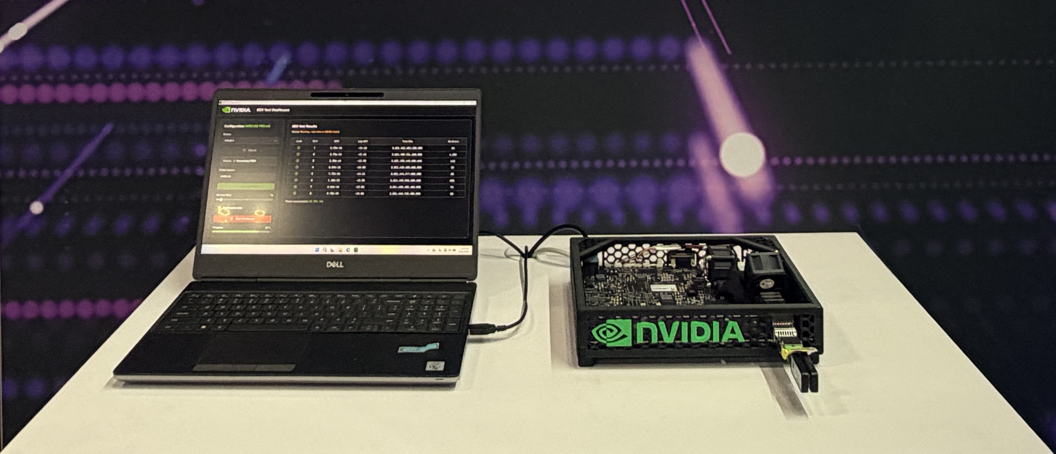
Image context: Lumentum-enabled optical transceiver demonstration in the existing BitcoinVersus.Tech media library. For engineering fundamentals, consult EXFO’s optical return loss glossary and the Fiber Optic Association’s OTDR technical reference.
Worked example: combining reflected power
Suppose a simplified optical path has two isolated reflective events. The first reflects −40 dB of incident power and the second reflects −45 dB, both expressed relative to the same incident-power reference for this example. Their linear fractions are 10⁻⁴ = 0.0001000 and 10⁻⁴⋅⁵ ≈ 0.00003162. The total reflected fraction is approximately 0.00013162. The resulting idealized ORL is −10 log₁₀(0.00013162) ≈ 38.81 dB.
Notice that 38.81 dB is less than the 40 dB ORL that would correspond to the first event alone. Adding a second reflection increased returned power and worsened aggregate ORL. Real systems require corrections for attenuation, distributed backscatter, instrument reference planes and other effects. This simplified arithmetic is a conceptual example, not a field certification procedure.
Measurement methods and interpretation
An OTDR can estimate the location and reflectance of individual events by comparing the reflected peak with its backscatter baseline. An optical return-loss meter can measure aggregate reflected power from a path under its specified reference procedure. The two instruments answer related but different questions: one locates and characterizes events, while the other can quantify total return under defined conditions.
The following existing optical equipment image provides a second relevant view of high-capacity transport hardware and fiber connections. Such systems may be sensitive to reflection budgets across connectors, multiplexers and optical line equipment.

A practical engineering workflow starts by confirming the test wavelength, fiber type, launch and receive conditions, connector polish and instrument calibration. Then compare measured event reflectance and path ORL with the requirements of the actual transceiver and system design. OSFOTC.003 explains OTDR setup and dead zones, while OSFOTC.009 covers formal link acceptance.
Connector polish and design implications
Angled physical contact (APC) connectors redirect much of the reflected light away from the guided return path and are used in applications where low back-reflection is especially important. Ultra physical contact (UPC) connectors use a different end-face geometry. These connector types are not interchangeable simply because their ferrules fit similar housings. Never mate APC and UPC interfaces unless the manufacturer explicitly approves the connection.
Engineers designing long-haul coherent systems, dense wavelength-division multiplexing links or sensitive analog optical links must consider reflection limits along with insertion loss, optical signal-to-noise ratio and dispersion. Review OSFOEC.007 on coherent transmission, OSFOEC.010 on performance telemetry, and OSFOTC.004 on connector types.
Safety and troubleshooting
Never look into an active fiber or optical port; infrared laser light may be invisible. Before disconnecting a live circuit, follow the operator’s approved change-control and optical safety procedures. If ORL is worse than expected, inspect and clean connector end faces, verify polish compatibility, check for damaged jumpers or unprotected terminations, and compare OTDR events with as-built records. Re-test only under the applicable site and equipment procedures.
Knowledge check
- Why is individual-event reflectance normally reported as a negative dB value?
- What does a larger positive optical return loss value indicate?
- Why can a link have acceptable insertion loss but still fail a return-loss requirement?
Answers: Reflected power is a fraction below incident power, so its logarithmic ratio is negative; less total returned power; reflection is a separate optical impairment from forward attenuation.
References and related reading
For further study, see EXFO on optical return loss, FOA on OTDR testing, and the relevant manufacturer test procedures and optical-interface specifications. The ITU-T G.650.3 recommendation describes test methods for installed single-mode optical fiber cable links.
BitcoinVersus.Tech Editor’s Note: Help sustain independent optical engineering education with a contribution of 5,000 sats. Scan the Bitcoin QR code below with your wallet to support future lessons.

Display the QR code on another screen and scan it using a compatible Bitcoin wallet.


Leave a Reply