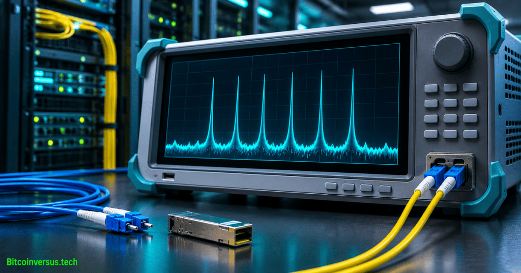
Optical signal-to-noise ratio (OSNR) is the ratio of useful optical signal power to optical noise power within a specified reference bandwidth. Expressed in decibels (dB), OSNR helps engineers evaluate the quality of light signals transmitted through fiber-optic networks, especially amplified dense wavelength-division multiplexing (DWDM) links. Higher OSNR indicates greater separation between a signal and its noise floor, although adequate power and OSNR alone do not guarantee error-free data.
Modern fiber networks can carry multiple wavelengths through one strand. Each wavelength functions as a separate optical channel, and an optical receiver must distinguish the encoded information from random light fluctuations. OSNR therefore measures a different property from received power: the separate dBm reference describes absolute power, whereas OSNR describes the ratio between signal and noise.
Definition and mathematical expression
For signal power Ps and noise power Pn evaluated under the specified bandwidth convention, OSNR (dB) = 10 log10(Ps/Pn). When both values are expressed in dBm with matching references, OSNR (dB) = Ps (dBm) − Pn (dBm). The result is a ratio in dB, never dBm.
Optical noise power changes with the measurement bandwidth. ITU-T optical-system guidance commonly normalizes OSNR to a 0.1-nanometer (nm) reference bandwidth. Any quoted OSNR should identify the bandwidth and measurement method; comparing readings from different bandwidths without normalization can be misleading.
Worked optical-power example
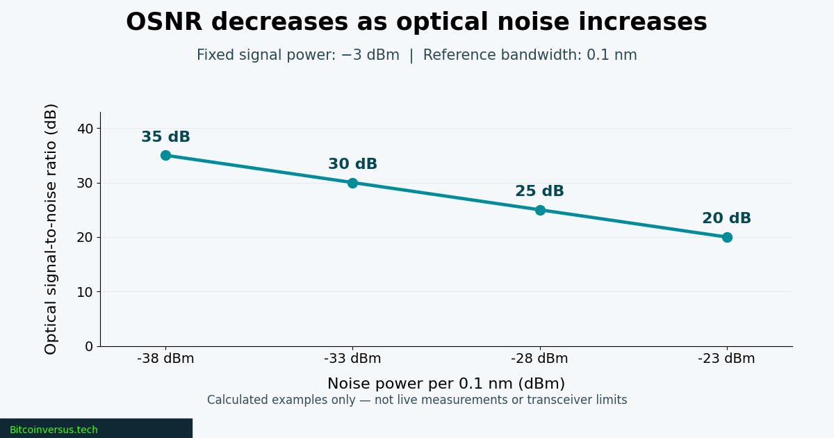
Suppose a hypothetical channel carries −3 dBm of signal and −28 dBm of optical noise, with noise already normalized to 0.1 nm. The ratio is −3 − (−28) = 25 dB, equivalent to about 316 times as much signal power as noise power under the stated convention. If noise rises to −23 dBm while signal stays at −3 dBm, OSNR falls to 20 dB, or 100:1. Neither example represents a specific product or deployment.
Where optical noise originates
One common impairment is amplified spontaneous emission (ASE) produced by optical amplifiers such as erbium-doped fiber amplifiers (EDFAs). An amplifier can restore signal strength after a fiber span while adding noise. With multiple spans, accumulated ASE can reduce OSNR even when output power appears normal. The site’s optical-amplification engineering lesson explains gain, noise figure and span planning.
Channel filtering, amplifier loading and wavelength-selective components can reshape the noise spectrum. A noise measurement taken between channels might therefore fail to represent noise beneath a data channel. Engineers designing DWDM channel plans must account for frequency spacing, optical filters and the applicable measuring technique.
HUBER+SUHNER, “OSNR explained (01-04-08),” published March 4, 2026. Manufacturer educational video describing noise, optical amplification, measurement and the relationship between OSNR and bit errors.
Measurement and receiver performance
An optical spectrum analyzer (OSA) can estimate channel power and the surrounding spectral noise floor. However, conventional out-of-band interpolation may misrepresent noise under heavily filtered channels. The International Telecommunication Union’s G.697 optical-monitoring recommendation addresses optical-network monitoring; its August 2026 revision introduces additional OSNR calculation guidance. Measurement methods, reference bandwidth and equipment limitations matter when comparing results.
OSNR requirements also depend on modulation format, baud rate, receiver implementation and forward-error correction (FEC). A coherent receiver using higher-order modulation generally needs cleaner signals than a more noise-tolerant configuration. Cisco’s coherent-modulation explanation discusses the trade-off, while coherent transmission engineering provides additional background.
OSNR, dBm and bit-error rate
OSNR, received dBm and bit-error rate (BER) answer different questions. dBm measures absolute light power; OSNR characterizes signal relative to optical noise; and BER counts incorrect bits relative to the number of bits evaluated. A system can retain adequate received power while its OSNR deteriorates. The optical-performance monitoring lesson explains why operators trend OSNR alongside FEC and receiver telemetry instead of treating one metric as an end-to-end guarantee.
References
ITU-T G.697 (August 2026), current optical-monitoring recommendation; ITU-T G Supplement 39 (October 2025), optical-system design; Cisco, Coherent Optical Modulation (October 2023). The publicly available 2016 G.697 edition documents established out-of-band and in-band measurement caveats; the 2026 edition supersedes it.
BitcoinVersus.Tech Editor’s Note
Reviewed November 8, 2026. Formulas and chart figures are calculated teaching examples, not live traffic or calibrated instrument data. The featured image is conceptual artwork and does not depict a verified vendor instrument. The video is provided for technical education; its presence does not establish a field benchmark or independent playback test.
We volunteer daily to ensure the information on this platform is Verifiably True. If you would like to support the research, please scan QR code.

Readers may support independent reporting with an optional 5,000-satoshi donation. Scan the original QR using a Bitcoin wallet and verify destination 3C9o19EH5HSiwEPyCTmEKzxhNCbo2X6TTb and the payment amount before sending.
BitcoinVersus.Tech is not a financial advisor. Financial coverage is provided purely for informational purposes.


Leave a Reply