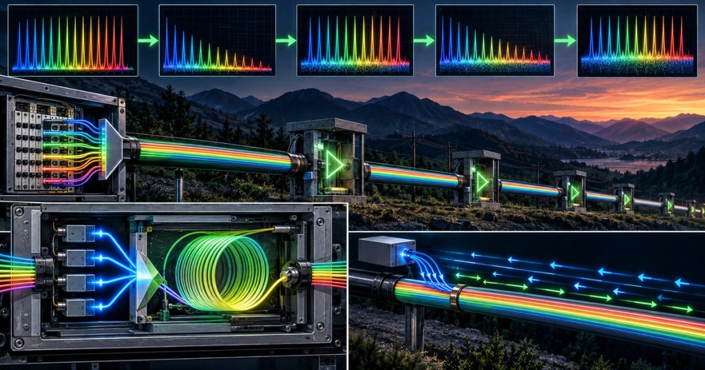
Elementary Overview
Optical amplifiers increase light power directly in the optical domain so a DWDM system can carry many wavelengths farther without converting every channel to electrical form at each span. The engineering challenge is that an amplifier restores power but does not restore the original signal quality. Fiber attenuation, filtering, dispersion, nonlinear effects, and amplifier noise still accumulate across the path. This lesson follows OSFOEC.005 DWDM Channel Planning and connects to older BitcoinVersus.Tech lessons on attenuation, fiber characterization, and WDM.
EDFA: The C-Band Workhorse
An Erbium-Doped Fiber Amplifier uses erbium-doped fiber energized by a pump laser, commonly near 980 nm or 1480 nm, to amplify signals around the 1550 nm region. EDFAs can work as booster amplifiers after a transmitter, inline amplifiers between spans, or preamplifiers near a receiver. Cisco describes EDFA as a key enabling technology for long-distance DWDM because many wavelengths can be amplified together. This builds directly on OSFOEC.001 optical link budgets.
Gain, Saturation, and Gain Flatness
Optical gain tells the engineer how much the amplifier raises signal power. In field units, Gain (dB) = Pout (dBm) − Pin (dBm). A channel entering at −18 dBm and leaving at +2 dBm received 20 dB of gain. Real design also checks total composite output power, per-channel power, gain ripple, saturation, and gain flatness across the DWDM band. That is why a high-gain amplifier is not automatically a better amplifier. Older BitcoinVersus.Tech training on insertion loss provides the opposite side of the same power-budget equation.
ASE Noise and Noise Figure
EDFAs also create Amplified Spontaneous Emission, or ASE. Random spontaneous photons generated inside the gain medium are amplified along with the useful signal, raising the optical noise floor. In cascaded links, ASE from one amplifier is carried into later amplifiers and can be amplified again. EXFO uses noise figure to quantify this signal-to-noise degradation, which is why two amplifiers with the same nominal gain can produce different end-to-end performance. Engineers therefore measure gain and noise behavior with optical spectrum analysis instead of judging health from output power alone.
Raman Amplification Uses the Span Fiber
Raman amplification uses high-power pump light and stimulated Raman scattering to transfer energy into the data signal. In distributed Raman systems, the transmission fiber itself becomes part of the gain medium, often with pump light traveling opposite the data direction. Cisco notes that Raman can add effective span gain while degrading OSNR less than simply inserting another EDFA, so it is useful when a link is noise-limited rather than merely power-limited. Hybrid Raman-plus-EDFA systems are common in difficult long-haul designs.
OSNR Is the Key Quality Metric
Optical Signal-to-Noise Ratio compares optical signal power with optical noise power in the same reference bandwidth. In the simplest dB form, OSNR = Signal Power (dBm) − Noise Power (dBm). Amplifier chains can restore channel power after every span while OSNR gets worse because ASE accumulates. For approximately identical amplified spans, a useful first estimate is an OSNR penalty of about 10 log10(N) as the number of similar spans N increases, but real systems must also include actual gain, filtering, channel loading, baud rate, modulation, nonlinear effects, and FEC. That connects directly to OSFOEC.004 high-speed signaling and early-2026 PMD training.
Span Planning Ties Power, Noise, and Spectrum Together
A complete amplified-span design tracks transmitter power, mux loss, fiber loss, connector and splice loss, amplifier input power, required gain, total output power, per-channel power, gain ripple, OSNR, ROADM/WSS filtering, and receiver requirements. Amplifiers should not be placed at a fixed distance without calculating the actual loss and noise budget. Modern optical line systems combine amplifiers with channel monitors, dynamic gain equalization, and wavelength-selective switches, so power engineering and spectrum engineering are tightly connected.
Worked Span Example
- Transmitter power: +0 dBm per channel.
- Mux and patch loss: 4 dB.
- Fiber: 80 km × 0.20 dB/km = 16 dB.
- Splice/connector allowance: 1 dB.
- Amplifier input: about −21 dBm per channel.
- Target EDFA gain: about 20 dB, subject to input range, total power, gain flatness, and design margin.
- Approximate output: about −1 dBm per channel before downstream losses.
- Final check: verify OSNR and receiver margin; restored power alone does not prove the span is healthy.
Engineering Checklist
- Map every span, splice, connector, mux, WSS/ROADM, and passive loss.
- Calculate per-channel and total composite optical power.
- Identify each amplifier as booster, inline, preamplifier, Raman, or hybrid.
- Verify input range, output limit, gain, gain ripple, and saturation margin.
- Model ASE accumulation and end-to-end OSNR.
- Confirm required OSNR, BER, and FEC margin for the selected transceiver.
- Check channel loading and transient behavior when wavelengths are added or removed.
- Measure with an optical spectrum analyzer or optical channel monitor where available.
- Document amplifier settings, measured span loss, OSNR, and final design margin.
Exercises
- A channel enters an EDFA at −17 dBm and exits at +3 dBm. Calculate the gain.
- Explain why adding 20 dB of gain does not restore OSNR lost in previous spans.
- Describe booster, inline, and preamplifier placement.
- Explain why Raman amplification can help a noise-limited span.
- Build a two-span power budget with fiber loss, mux loss, two amplifiers, and receiver power.
- Explain why channel loading matters in a DWDM amplifier system.
Knowledge Check + Answers
- What does EDFA stand for? Erbium-Doped Fiber Amplifier.
- What is the simple gain equation? Gain = Pout(dBm) − Pin(dBm).
- What is ASE? Amplified Spontaneous Emission, optical noise created and amplified inside an optical amplifier.
- What does noise figure describe? How much the amplifier degrades signal-to-noise performance.
- What does OSNR compare? Optical signal power with optical noise power in the same reference bandwidth.
- Why is Raman amplification different? Distributed Raman can use the transmission fiber itself as part of the gain medium.
- Does adequate receive power prove the link is healthy? No. OSNR, BER/FEC margin, dispersion, nonlinear penalties, and filtering still matter.
Elementary Conclusion
- Core rule: plan gain and noise together. EDFA restores power, Raman can improve difficult spans, and OSNR tells you whether the amplified signal remains clean enough to decode.
Primary references: Cisco DWDM Engineering and Planning Guide; Cisco Optical Amplifier Cards; EXFO EDFA Gain and Noise Figure; Nokia Hyperscale Optical Line Systems.
Editor’s Note
BitcoinVersus.Tech publishes this lesson for technical education and reference. BitcoinVersus.Tech is not a financial advisor.


Leave a comment