Elementary Overview
A fiber link can fail even when the cable is unbroken and the connectors appear normal. Dust, oil, scratched end faces, poor reference setup, wrong wavelength, dirty test cords, and excessive connector or splice loss can all reduce received optical power. A technician therefore follows a repeatable sequence: inspect and clean, establish a reference, measure the link, compare the result with the allowed loss, record the evidence, and troubleshoot only when the measurement is trustworthy. This lesson turns the individual skills from OSFOTC.002 optical power-meter basics, OSFOTC.003 OTDR testing, and OSFOTC.004 connector and polarity verification into one field workflow.
Inspect And Clean Before You Reference
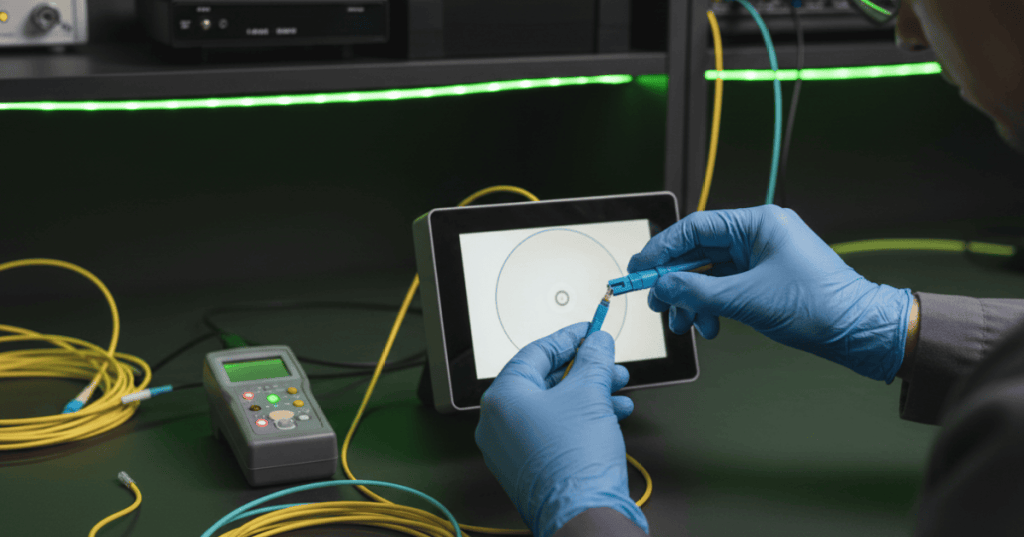
The test set is only as trustworthy as the interfaces connecting it to the fiber. Inspect the connector end face with an appropriate fiber inspection scope, clean when contamination is present, and inspect again before mating. Never look directly into an active fiber with an optical microscope, and follow the safety method established in OSFOTC.001. Clean both the link connector and the reference test cords, protect unused adapters with caps, and avoid touching ferrule end faces. If a reference cord is dirty while the zero reference is established, every later result can inherit that error.
Set The Reference Before Measuring Link Loss
An optical loss test set combines a stabilized light source with an optical power meter. First select the wavelength required for the fiber and test plan, connect known-good reference cords using the required reference method, and store the reference value. The link loss is then the difference between the reference power and measured power: Loss (dB) = Reference Power (dBm) − Measured Power (dBm). If the stored reference is −2.0 dBm and the far-end measurement is −4.3 dBm, the measured insertion loss is 2.3 dB. The reference method must remain consistent because adding or removing test-cord connections changes what the measurement includes.
Measure, Compare, Record, Then Troubleshoot
After the reference is established, connect the fiber under test without disturbing the reference connection that the procedure requires you to keep fixed. Measure at the specified wavelength or wavelengths, record the measured loss, and compare it with the project acceptance limit or calculated loss budget. A passing number should still be documented with fiber ID, endpoints, wavelength, direction, test-set IDs, reference method, date, and technician. If the result fails, inspect and clean first, verify polarity and connector type, repeat the reference check, then use a VFL for simple continuity or visible faults and an OTDR when the location and character of loss events must be identified.
Field Workflow
- Confirm the fiber ID, endpoints, fiber type, connector type, and required test wavelength.
- Verify the link is safe to test and disconnect active optics when the procedure requires it.
- Inspect the reference-cord and link end faces.
- Clean contaminated end faces and inspect again.
- Power on the light source and power meter and allow any required stabilization time.
- Select the correct wavelength on both instruments.
- Connect the required reference-cord arrangement.
- Store the reference value and document the reference method.
- Connect the fiber under test without changing the fixed reference connection.
- Measure loss in dB at each required wavelength and direction.
- Compare measured loss with the acceptance limit.
- Save the result with fiber ID, endpoints, direction, wavelength, instrument IDs, and date.
- If the link fails, inspect/clean again, verify polarity, verify the reference, then isolate the fault with VFL or OTDR as appropriate.
Worked Example
- Reference power: −1.5 dBm
- Measured far-end power: −3.4 dBm
- Measured loss: (−1.5) − (−3.4) = 1.9 dB
- Project maximum: 2.4 dB
- Result: PASS, with 0.5 dB remaining before the acceptance limit.
- Record: fiber ID, A/B endpoints, wavelength, direction, reference method, instrument IDs, date, and technician.
Fast Troubleshooting Order
- Inspect the end faces.
- Clean and inspect again.
- Confirm connector type and polarity.
- Confirm wavelength and fiber type.
- Recheck the stored reference with the reference cords.
- Replace a suspect reference cord or adapter.
- Repeat the loss measurement.
- Use a VFL for continuity, bends, or nearby visible faults where appropriate.
- Use an OTDR to locate reflective and non-reflective loss events.
- Repair the physical cause and retest from the beginning of the acceptance workflow.
Exercises
- A reference is −3.0 dBm and the measured value is −5.2 dBm. Calculate insertion loss.
- Explain why a dirty reference cord can corrupt every later test.
- Name the information that should be saved with a passing loss measurement.
- Explain when a VFL is more useful than an OTDR and when an OTDR is more useful than a VFL.
- A link measures 2.8 dB against a 2.5 dB maximum. Write the first five troubleshooting actions in order.
- Explain why the test wavelength must match the test plan and fiber application.
Knowledge Check + Answers
- What should happen before mating or testing a fiber connector? Inspect it, clean it when necessary, and inspect again.
- What two instruments form the basic OLTS measurement? A stabilized optical light source and an optical power meter.
- How is insertion loss calculated from dBm readings? Reference power minus measured power, producing a positive loss value in dB for a normal lossy link.
- What is the answer to Exercise 1? (−3.0) − (−5.2) = 2.2 dB.
- What should a technician do first after an unexpected high-loss result? Verify the measurement itself by inspecting/cleaning connections and checking the reference before assuming the installed fiber is damaged.
- Why record wavelength and direction? Because optical loss can differ by wavelength and direction, and repeatable acceptance evidence requires both.
- What does an OTDR add after a failed OLTS test? Distance-resolved evidence that can help locate connectors, splices, bends, breaks, and other loss or reflection events.
Elementary Conclusion
- Inspect and clean first.
- Reference the instruments correctly.
- Measure at the required wavelength.
- Compare the result with the approved loss limit.
- Record enough evidence for another technician to repeat the test.
- Troubleshoot the measurement path before blaming the installed fiber.
BitcoinVersus.Tech
Advertisement
Editor’s Note: We volunteer daily to keep the technical information on this platform verifiable. Readers who want to support the research can use the donation information published by BitcoinVersus.Tech.
BitcoinVersus.tech is not a financial advisor. This media platform reports on financial subjects purely for informational purposes.


Leave a comment