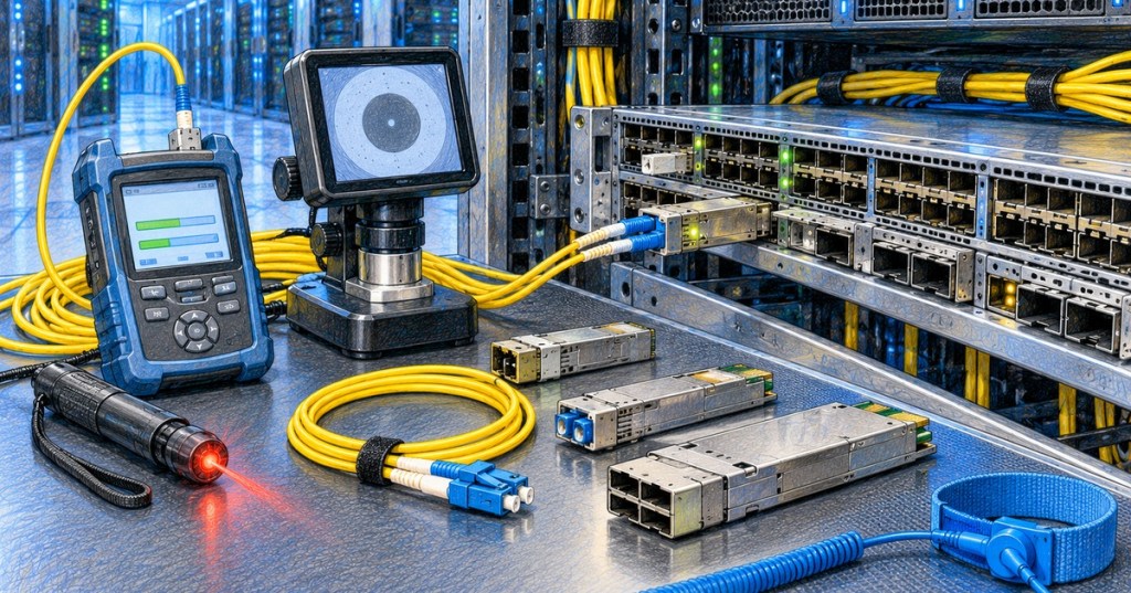
Optical transceivers convert electrical data inside a switch, router, or server NIC into light on fiber and convert received light back into electrical data. For a fiber technician, the important skill is not only identifying SFP or QSFP modules. It is proving that the optic, fiber plant, polarity, wavelength, receive level, host port, and configuration all agree before replacing hardware.
This lesson follows OSFOTC.009: Fiber Optic Link Testing and Certification. Certification proves the passive fiber plant. OSFOTC.010 moves one layer outward into the active optics installed at each end of that plant.
This technician-focused data-center lesson introduces SFP, SFP+, SFP28, and QSFP-family transceivers and the differences among their form factors and speeds.
Elementary Overview
A fiber cable carries light, but a network switch works with electrical signals. The transceiver is the small removable module that connects those two worlds. If the wrong module is installed, if the fiber strands are reversed, if the connector is dirty, or if too little light reaches the receiver, the link may stay down even when the cable itself is intact.
Learning Objectives
- Identify common SFP and QSFP transceiver families.
- Match optic speed, wavelength, fiber type, reach, and connector type to the link.
- Install and remove pluggable optics using ESD-safe practices.
- Interpret Digital Optical Monitoring values such as Tx power, Rx power, temperature, voltage, and laser-bias current.
- Distinguish an optic fault from a dirty connector, bad patch cord, polarity problem, unsupported module, or damaged fiber plant.
- Use known-good substitutions without losing the original fault evidence.
- Document a transceiver replacement so the next technician can reproduce the diagnosis.
Know the Form Factor Before Touching the Link
SFP, SFP+, and SFP28 share a small single-lane form factor but are commonly associated with different generations of Ethernet speed. QSFP+, QSFP28, QSFP-DD, and related formats use multiple electrical lanes and support higher aggregate rates. A cage that looks mechanically compatible does not guarantee that every module speed or coding mode is supported by the host platform.
The module label and vendor compatibility documentation should be checked before installation. Record the exact part number, wavelength, reach class, connector type, nominal data rate, and whether the module is single-mode, multimode, BiDi, parallel-optic, WDM, DAC, or AOC.
Match Both Ends of the Optical Link
Two modules must be compatible as a pair. Ordinary duplex optics generally need matching Ethernet standards and wavelengths at both ends. A short-reach multimode optic should not be paired with a long-reach single-mode optic merely because both use LC connectors. BiDi optics are a special case: the transmit wavelength on one end must correspond to the receive wavelength on the opposite end.
Cisco’s SFP installation guidance explicitly requires compatible wavelength specifications at both ends and a cable length within the supported reach. The fiber type matters as well. An optic designed for OS2 single-mode fiber and one designed for OM4 multimode fiber use different optical launch conditions even if the patch cords can be physically connected.
Install the Module Without Damaging It
Pluggable optics are static-sensitive devices. Use the site-approved ESD procedure and an ESD wrist strap or equivalent grounding method when required by the equipment manufacturer. Keep dust plugs installed until the optical interface is ready to be inspected and connected.
Cisco also warns against repeatedly removing and reinserting optics without need. Disconnect the fiber before removing the transceiver, release the correct latch or bail mechanism, and avoid forcing a module into a cage with the wrong orientation. After insertion, verify that the module is fully seated and latched.
Fluke Networks demonstrates a non-contact method for confirming whether SFP and QSFP transmitters are emitting light during field troubleshooting.
Inspect and Clean Before Connecting
A clean certified fiber can become a bad link as soon as it is connected to a contaminated patch cord or dirty transceiver interface. Use the inspect-clean-inspect workflow from OSFOTC.001. Never look directly into an unknown or potentially active fiber.
Fluke Networks identifies connector contamination as a leading cause of fiber failures. Cleaning should be done with the correct optical-grade tools, and inspection should confirm that the end face is clean before mating it to the optic.
Fluke Networks explains fiber inspection and cleaning practices used to prevent contamination-related loss and repeat failures.
Verify Polarity
On an ordinary duplex optical link, the transmitter at Side A must reach the receiver at Side B, and the transmitter at Side B must reach the receiver at Side A. If both transmitters land on the same strand position, the link remains down even though both optics and both fibers may be healthy.
Review OSFOTC.004: Fiber Connector Types and Polarity for duplex LC and MPO/MTP polarity. Do not roll fibers randomly on a production link without recording the original orientation.
Digital Optical Monitoring Is the First Active Diagnostic
Many modern transceivers report internal telemetry through Digital Optical Monitoring, often shortened to DOM or DDM. Cisco and Juniper document real-time values including transmit optical power, receive optical power, module temperature, supply voltage, and laser-bias current. Higher-lane-count optics can report these values separately by lane.
On Cisco platforms the exact command varies by operating system, but a common family is show interfaces transceiver. Junos provides show interfaces diagnostics optics <interface-name>. Always use the command appropriate to the actual platform rather than copying syntax blindly from another vendor.
Read Tx and Rx Power in dBm
Tx power is the optical power the local transmitter reports sending. Rx power is the optical power the local receiver reports receiving from the far end. Values are commonly shown in dBm. A more negative dBm value means less optical power. For example, -12 dBm is weaker than -4 dBm.
Do not use a universal “good” dBm number. Compare each reading with the warning/alarm thresholds and receive range for that specific module. A long-reach optic may have very different allowable levels from a short-reach optic. Excessively high receive power can be a problem just as excessively low power can be.
A Simple Directional Diagnosis
- Local Tx normal, local Rx near zero or below threshold: investigate the far-end transmitter, remote patching, polarity, contamination, fiber loss, or break in the receive direction.
- Local Tx low or alarmed: investigate the local optic, cage, module temperature, host compatibility, or transmitter fault.
- Both ends report normal optical levels but link stays down: investigate speed, FEC, autonegotiation, breakout mode, encoding, unsupported optic, interface configuration, or higher-layer issues.
- One lane is bad on a multi-lane optic: inspect per-lane DOM, MPO polarity, individual fibers, lane mapping, and the optic itself.
This transceiver troubleshooting webinar focuses on isolating 100G optic faults instead of replacing both sides blindly.
Do Not Replace Both Optics at Once
Replacing both transceivers at the same time may restore service, but it destroys useful fault isolation evidence. When operational risk allows, change one variable at a time. A known-good optic, known-good patch cord, alternate port, or loopback can help isolate the failure without turning the troubleshooting process into guesswork.
A data-center networking discussion highlights the same diagnostic lesson: swapping both optics can fix a link while leaving the actual failed component unidentified.
Use a Known-Good Path Carefully
A known-good substitution is strongest when only one component changes. If a suspect optic works in a known-good port with a known-good patch cord and compatible far-end optic, that is useful evidence. If the fault follows the optic across ports, suspicion increases further. If the fault remains on the original path after replacing the optic, return attention to the fiber plant, patching, port configuration, or host hardware.
Do not move questionable optics or dirty patch cords into unrelated production paths without authorization. Troubleshooting should not create a second outage.
Loopback Testing
A properly designed optical loopback can test whether a port and optic can transmit and receive locally, but the method must match the module type and optical power limits. Never loop a high-power long-reach transmitter directly into a sensitive receiver unless the manufacturer’s specifications show that the resulting receive power is safe. Optical attenuation may be required.
When the Passive Fiber Plant Is Suspect
If DOM shows a healthy transmitter but weak or missing receive power, inspect and clean the end faces, verify polarity, substitute patch cords, then test the installed link. Use the OLTS workflow from OSFOTC.005 or the certification workflow from OSFOTC.009. Use an OTDR when event location is needed.
Fluke Networks demonstrates fiber inspection and cleaning tools used before blaming an optical module for excessive loss.
Unsupported Optic Versus Failed Optic
A physically installed transceiver can be electrically healthy but rejected by the host platform. Some switches validate module identification, supported part numbers, firmware, coding, or vendor information. Check logs and inventory output for unsupported-transceiver messages before declaring the optic defective.
Likewise, a 100G or 400G port may need a specific breakout or lane configuration before lower-speed channels operate. The module and cable can be healthy while the interface is configured for the wrong mode.
Temperature and Bias Current Are Clues
DOM temperature, supply voltage, and laser-bias current provide additional evidence. A transceiver operating near a thermal alarm may show intermittent errors or deteriorating optical performance. Bias current that approaches an alarm threshold can indicate the laser is being driven unusually hard, although the interpretation depends on the module design and vendor thresholds.
Trend data is more useful than one isolated reading. If Rx power slowly declines over weeks while Tx power remains stable, contamination, connector degradation, fiber movement, bend stress, or remote-side transmitter aging may deserve investigation.
Technician Troubleshooting Sequence
- Record the exact interface, host device, optic part number, serial number, speed, wavelength, fiber type, and far-end interface.
- Confirm the interface is administratively enabled and in the intended speed/FEC/breakout mode.
- Check logs for unsupported-module, loss-of-signal, high-temperature, low-Rx, or other transceiver alarms.
- Read DOM values on both ends before disturbing the link.
- Confirm the optic standards and wavelengths match.
- Verify the fiber type and connector type.
- Inspect, clean, and reinspect patch-cord and bulkhead end faces.
- Verify duplex or MPO polarity.
- Substitute one known-good patch cord if allowed.
- Substitute one known-good optic at one end if allowed.
- Use an approved live-fiber detector, optical power meter, OLTS, or OTDR when the passive path remains suspect.
- Compare the suspect component in a known-good path only when change-control and operational risk allow.
- Restore the original labeling and cable routing after the test.
- Record the final root cause and all replaced serial numbers in the ticket.
Common Failure Patterns
- Link down, no local Tx light: local optic, cage, power, admin state, or unsupported-module issue.
- Local Tx normal, Rx absent: remote transmitter, polarity, dirty connector, open fiber, or severe loss.
- Rx just above low-warning threshold: inspect cleanliness, patching, link budget, bends, connector count, and aging margin.
- Rx too high: verify optic reach and receiver maximum; attenuation may be required for some long-reach links.
- DOM good, link still down: check speed, FEC, PCS/lane mode, autonegotiation, coding, host compatibility, and configuration.
- One lane bad on QSFP-class optic: check individual lane telemetry, MPO strand mapping, parallel-fiber continuity, and the module.
- Intermittent errors only when warm: review module temperature, airflow, cage condition, and temperature alarms.
- New optic fails only in one switch: check host support, firmware, cage damage, configuration, and port hardware before condemning the optic.
Hands-On Exercise
Build a lab link with two compatible optical ports and a duplex fiber jumper. Record both optics’ part numbers, Tx power, Rx power, temperature, and alarm thresholds. Then create one controlled fault at a time: reverse polarity, disconnect one strand, contaminate only a disposable training connector under approved lab procedure, or replace one optic with an intentionally incompatible lab module.
For each condition, predict the DOM pattern before looking at the result. Restore the clean known-good state between tests. The objective is to connect symptoms with directional evidence instead of memorizing a list of replacement steps.
Knowledge Check
- What does an optical transceiver do?
- Why can two LC optics still be incompatible with each other?
- What does DOM commonly report?
- Which is weaker: -3 dBm or -13 dBm?
- Why should Tx and Rx power be checked before swapping parts?
- Why is replacing both optics at once a weak troubleshooting method?
- What should be checked when DOM is healthy but the Ethernet link remains down?
- Why can excessive receive power be a problem?
Answers
- It converts electrical data into optical signals for transmission and converts received optical signals back into electrical data.
- They may use different wavelengths, fiber types, Ethernet standards, lane arrangements, reaches, or BiDi pairings even though the connector physically fits.
- Typically Tx power, Rx power, temperature, supply voltage, laser-bias current, and warning/alarm thresholds; multi-lane modules may report per-lane values.
- -13 dBm is weaker because it is more negative.
- The readings preserve directional evidence that helps separate transmitter, receiver, optic, fiber, polarity, and configuration faults.
- It changes two variables at once and can restore service without revealing which component was actually bad.
- Speed, FEC, breakout/lane mode, autonegotiation, coding, host compatibility, interface configuration, and higher-layer state.
- A receiver has a maximum safe/valid optical input; too much light can overload the receiver or violate its specification.
Elementary Conclusion
The fastest way to troubleshoot fiber optics is to avoid guessing. Check what the module is, what light it should send, what light it actually receives, whether the fiber is clean and crossed correctly, and whether the host port is configured for the same technology. Change one thing at a time and preserve the evidence.
Previous Related Lessons
- OSFOTC.009: Fiber Optic Link Testing and Certification
- OSFOTC.008: Fiber Troubleshooting and Restoration
- OSFOTC.005: Optical Loss Testing Workflow
- OSFOTC.004: Fiber Connector Types and Polarity
- OSFOEC.003: Optical Transceiver Selection Engineering
Primary References
- Cisco — SFP and SFP+ Transceiver Module Installation Notes
- Cisco — Digital Optical Monitoring Statistics
- Juniper Networks — Digital Optical Monitoring
- Juniper Networks — show interfaces diagnostics optics
- Fluke Networks — How to Test an SFP Transceiver and Network Cable
BitcoinVersus.Tech Editor’s Note:
We volunteer daily to ensure the credibility of the information on this platform is Verifiably True. If you would like to support to help further secure the integrity of our research initiatives, please donate using the QR code provided

For best QR-code scanning results, please scan this donation code from a desktop or larger screen. Mobile screens may prevent camera recognition.
BitcoinVersus.Tech provides technical education and analysis for informational purposes only.


Leave a Reply