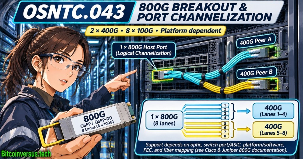
OSNTC.043 explains how one high-capacity Ethernet host port can become several lower-speed interfaces through breakout, also called port channelization. A supported 800G port might operate as one 800 Gigabit Ethernet interface, two 400G interfaces or eight 100G interfaces. Those are alternative configurations, not extra aggregate bandwidth. The subject follows OSNTC.042 on OSFP and QSFP-DD form factors, which distinguishes module shells from actual optical interoperability.
FS.com, “How to Connect OSFP and QSFP-DD Ports,” September 23, 2025. The manufacturer explains physical compatibility and illustrates 800G-to-2×400G breakout beginning around 02:08. Educational supplier demonstration, not a universal equipment approval. Credit: FS.com / YouTube.
Eight host lanes do not mean eight interchangeable fibers
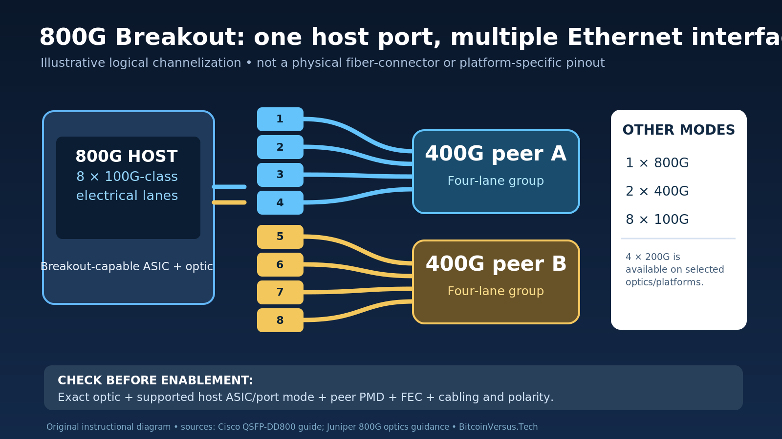
A conventional 800G client interface can use eight 100G-class host electrical lanes. The arithmetic is 8 × 100 Gb/s = 800 Gb/s, or a nominal 100 GB/s before Ethernet and application overhead. A 2×400G configuration assigns a logical four-lane group to each 400G interface; an 8×100G configuration creates eight logical 100G interfaces where supported. Host electrical lanes, optical wavelengths and individual fibers are separate design variables. OSFOEC.004 explains PAM4 signaling and why electrical baud rate differs from user throughput.
Juniper’s 800G breakout guide lists 1×800G, 2×400G and 8×100G options. Cisco’s OSFP portfolio also advertises selected 4×200G capabilities. The supported combination must be checked against the specific transceiver, switch ASIC, software release and port group; a speed printed on an optic never establishes every breakout mode.
Physical cabling and peer optics still have to match
Breakout can be delivered through an approved direct-attach copper assembly, active optical cable or compatible parallel-optical transceivers with a correctly mapped fanout harness. An 800G DR8-to-two-400G DR4 design, for example, needs approved parallel single-mode optics and matching connectors, polarity, reach and optical power budgets. A wavelength-multiplexed coherent optic cannot be passively divided into separate fiber links merely by attaching a fanout cable. Cisco’s breakout white paper distinguishes active cables, direct-attach assemblies and breakout-capable optical modules.
QSFPTEK, “How to Interconnect OSFP and QSFP DD Ports in 400G800G AI Networks,” June 18, 2026. Manufacturer discussion includes 800G breakout, transceiver choice and cables; validate all examples against the local platform. Credit: QSFPTEK / YouTube.
Check the platform before changing a port
Cisco’s June 2026 IOS XR guidance identifies 2×400G and 8×100G support on selected Cisco 8000 hardware and releases, with model-specific port-pairing restrictions. Juniper similarly notes that channelizing one port can affect other ports sharing the same hardware resources. A configuration intended for one switch must not be copied blindly to a different line card.
Before an authorized change, record the exact product IDs, approved breakout mode, cable mapping, peer port speeds and FEC compatibility. Use read-only interface and transceiver telemetry to establish link, optical power, error-counter and FEC baselines. OSNTC.041 covers FEC mismatches, while OSFOTC.010 explains optic installation and safe troubleshooting.
Operational limit: Channelization can improve port density during mixed-speed migrations, but it does not multiply switch fabric capacity. Changing port modes can interrupt live connections, rename logical interfaces and invalidate existing monitoring or configurations. Only an authorized maintenance plan with rollback and verified peer compatibility can establish readiness.
Editor’s Note: Lesson content was checked against Cisco’s June 2026 breakout configuration guidance, Cisco’s 800G transceiver specifications and Juniper’s 800G optics documentation. Two manufacturer-hosted YouTube videos were identified through public listings; actual playback and responsive rendering remain separate checks. The original 1200 × 630 anime-style cover bears the neon-green Bitcoinversus.tech watermark, and the explanatory lane diagram is conceptual. No production switch, cable or interface was changed or tested.

BitcoinVersus.Tech publishes independent technical education through volunteer contributions. An optional 5,000-satoshi donation supports ongoing research. Scan the original QR from a second screen using a compatible Bitcoin wallet; when viewing on the same phone, use a wallet that supports importing a saved QR image. Verify recipient 3C9o19EH5HSiwEPyCTmEKzxhNCbo2X6TTb and amount independently before payment. Bitcoin transfers are generally irreversible.
We volunteer daily to ensure the information on BitcoinVersus.Tech is Verifiably True. Material is educational and informational, not an authorization to modify production networking equipment, certified engineering advice, financial advice or investment advice.


Leave a Reply