Elementary Overview
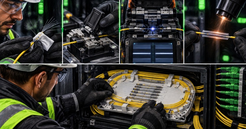
Fusion splicing permanently joins two optical fibers by precisely aligning their glass ends and using a controlled electric arc to fuse them together. For a fiber technician, the quality of the splice depends less on pushing the “splice” button and more on preparation: correct cable handling, coating removal, cleaning, an accurate cleave, clean splicer electrodes and V-grooves, proper fiber alignment, splice protection, and final testing. The Fiber Optic Association teaches the same sequence in its technician training, while manufacturers such as Sumitomo Electric and Corning emphasize clean preparation and repeatable low-loss results. This lesson follows OSFOTC.005 optical loss testing and builds on BitcoinVersus.Tech’s 2025 Fiber Optic Cabling and Fiber Optic Cabling Overview.
The Fusion-Splice Workflow
A practical workflow is prepare → strip → clean → cleave → load → align → fuse → inspect → protect → route → test. The technician first prepares the cable and identifies the correct fibers, then removes only the protective coating required for the splice. The bare glass is cleaned with approved lint-free materials and high-purity cleaning fluid, cleaved nearly perpendicular to the fiber axis, placed into the fusion splicer, aligned, fused, visually reviewed, covered with a splice-protection sleeve, heat-shrunk, and finally stored in a splice tray without violating bend-radius or strain-relief requirements. FOA’s hands-on training treats stripping, cleaving, splicing, testing, and tray placement as one connected workmanship process rather than isolated tasks.
Strip the Coating, Not the Cladding
A common terminology mistake is saying that a technician “strips the cladding.” The cladding is part of the glass optical fiber and must remain intact. What the technician removes is the polymer coating or buffer material around the glass. Remove the required length with the correct stripping tool, avoid nicking or scratching the glass, and immediately dispose of fiber shards in an approved container. Safety glasses remain mandatory because bare fiber fragments are small, sharp, and difficult to see. This connects directly to OSFOTC.001 safety, handling, inspection, and cleaning.
Cleaning and Cleaving Determine Splice Quality
After stripping, the bare glass must be clean before it enters the cleaver or splicer. Residue from coating, dirt, dust, skin oils, or contaminated tools can produce poor alignment, bubbles, weak joints, or excess optical loss. The cleaver then creates a controlled end face so the two fibers can meet correctly. A dirty cleaver blade, worn blade position, chipped fiber, incorrect strip length, or poor placement can create a bad cleave even when the technician follows the rest of the procedure correctly. If the splicer repeatedly rejects fibers, inspect and clean the cleaver and splicer before blaming the cable.
Alignment, Arc Fusion, and Estimated Loss
Inside the splicer, prepared fibers sit in precision holders or V-grooves while the machine images and aligns them. Depending on the splicer and fiber type, alignment may be based on the fiber cladding or on core-position information. The machine then applies a controlled electric arc that softens and joins the glass. After fusion, the splicer normally displays an estimated splice loss and may perform a proof test. Treat the displayed loss as a process indicator, not the final acceptance measurement. Project acceptance should rely on the approved test method—typically insertion-loss testing, OTDR analysis, or both—using the workflow already covered in OSFOTC.003 OTDR testing and OSFOTC.005 loss testing.
Protect and Route the Finished Splice
The fused glass joint is mechanically vulnerable until it is protected. Before splicing, technicians normally slide a heat-shrink splice-protection sleeve onto one fiber so it can be moved over the completed joint afterward. The sleeve is heated according to its design, allowed to cool, and placed into the correct holder in the splice tray. Corning describes splice trays as physical protection and fiber-organization hardware for fusion and mechanical splices, with strain-relief points and routing space intended to prevent induced attenuation from poor handling. The finished fiber should lie naturally in the tray with no sharp bends, pinches, crossing pressure, or tension on the splice.
Important: Do Not Accept a Splice From the Splicer Screen Alone
A visually clean splice with a low estimated loss can still require external verification. Record the fiber identifiers, direction, equipment used, estimated loss, test results, technician, and location according to the project procedure. If OTDR traces show an unexpected event or bidirectional loss is outside the project limit, remake or investigate the splice rather than assuming the machine estimate is correct. Also remember that not every optical impairment is caused by a splice; early-2026 BitcoinVersus.Tech training on Polarization Mode Dispersion covers another mechanism that can limit high-speed optical links.
Common Fusion-Splicing Problems
- Bad cleave: reclean if necessary, recleave with the correct length and blade position, then reload.
- Dirty V-groove or holder: clean according to the manufacturer procedure; contamination can move the fiber off-axis.
- Coating residue: restrip and clean the bare glass before another cleave.
- Arc or electrode warning: inspect electrode condition, perform calibration when required, and follow the splicer manufacturer’s maintenance procedure.
- Repeated high estimated loss: compare fiber types, verify cleaves, clean the system, check alignment, then confirm with external optical testing.
- Splice breaks during handling: review strip damage, cleave quality, fusion result, proof testing, and protection-sleeve handling.
- Good splice but high link loss: inspect connectors, bends, other splices, patching, launch conditions, and the complete optical path instead of remaking one splice blindly.
Field Checklist
- Confirm the correct cable, fiber count, color code, and splice plan.
- Wear safety glasses and prepare an approved fiber-shard container.
- Place the splice-protection sleeve on the fiber before fusion.
- Strip only the required coating or buffer length.
- Clean the bare glass with approved materials.
- Cleave the fiber with the correct tool and specified length.
- Keep the cleaver, fiber holders, V-grooves, lenses, and splicer work area clean.
- Load fibers without touching prepared glass ends.
- Review the splicer’s alignment image and warnings before fusion.
- Inspect the completed splice and note estimated loss.
- Center and heat the protection sleeve correctly.
- Route the protected splice into the tray without tight bends or strain.
- Test the completed link using the project’s approved loss or OTDR procedure.
- Record results and remake any splice that fails acceptance criteria.
Exercises
- Write the complete fusion-splice workflow from cable preparation through final testing.
- Explain why saying “strip the cladding” is technically incorrect.
- List four contamination points that can create a poor splice.
- Explain why cleave quality affects alignment and splice loss.
- Describe the difference between a splicer’s estimated loss and an accepted field measurement.
- Draw a splice tray and mark where strain relief, protected splices, and fiber slack should be organized.
- Create a troubleshooting sequence for repeated high-loss splice estimates.
Knowledge Check + Answers
- What does a fusion splicer actually join? The glass fibers after their protective coating has been removed and their ends have been properly prepared.
- What should be stripped from the fiber? The coating or buffer material—not the glass cladding.
- What is the purpose of the cleaver? To create a precise end face so two fibers can be aligned and fused with low loss.
- Why must bare fiber be cleaned before cleaving and splicing? Contamination can disrupt cleaving, alignment, fusion quality, and optical performance.
- What protects the finished fusion joint? A splice-protection sleeve placed over the fused joint and secured in the splice tray.
- Is the splicer’s estimated loss the final acceptance test? No. Acceptance follows the project’s approved optical test method.
- What should you do when several splices fail in the same way? Check preparation technique, cleaver condition, splicer cleanliness, alignment, electrodes/calibration, and fiber compatibility before repeatedly remaking splices.
Elementary Conclusion
Fusion splicing is a precision workmanship skill: strip, clean, cleave, align, fuse, protect, route, and test. The fusion splicer automates alignment and arc control, but it cannot compensate for dirty glass, a bad cleave, damaged fiber, contaminated tooling, poor tray routing, or skipped testing. A professional technician treats the splice as part of the complete optical path and verifies the result with the same measurement discipline taught in the earlier OSFOTC lessons.
Primary references: The Fiber Optic Association Guide to Fiber Optics; FOA Fiber U Splicing Skills Workbook; Corning Fusion Splicing; Corning Splice Trays.
Editor’s Note
We volunteer daily to help keep the information on this platform verifiably accurate. If you would like to support our independent research, please donate here: 3C9o19EH5HSiwEPyCTmEKzxhNCbo2X6TTb
BitcoinVersus.Tech is not a financial advisor. Content is provided for informational and educational purposes.


Leave a comment