Elementary Overview
Installing fiber cable is not simply a matter of getting the cable from Point A to Point B. A technician must protect the cable from excessive tension, tight bends, twisting, crushing, kinks, poor support, sharp edges, and careless storage while also leaving the route organized enough to test, troubleshoot, repair, and expand later.
This lesson follows OSFOTC.006: Fiber Fusion Splicing. Before that, OSFOTC.005: Optical Loss Testing Workflow and OSFOTC.003: OTDR Field Testing established how technicians verify optical performance. OSFOTC.007 moves upstream to the physical installation work that determines whether the cable reaches those tests in good condition.
What You Should Learn
- Why manufacturer cable specifications control installation limits.
- How bend radius changes while a cable is under pulling tension versus resting after installation.
- Why pulling tension must be applied through the cable’s approved strength system.
- How conduit, trays, ladders, sheaves, capstans, rollers, and guides protect the route.
- Why long pulls require planning, communication, tension monitoring, and sometimes intermediate assist points.
- How figure-eight handling prevents uncontrolled cable twist during staged pulls.
- How to manage slack and service loops without creating tight coils or congestion.
- How to support vertical and horizontal runs without crushing the cable.
- What to label and document during installation.
- How to perform an acceptance handoff using visual inspection and optical testing.
The Cable Specification Comes First
Fiber cables differ in diameter, strength members, armor, jacket material, fiber count, construction, installation method, and environmental rating. The Fiber Optic Association therefore recommends following the cable manufacturer’s installation instructions rather than assuming one universal tension or bend limit applies to every cable.
Before the pull begins, identify the cable model and verify at least its maximum installation tension, minimum bend radius while under tension, minimum long-term bend radius, crush limits, approved pulling attachment method, cable length, and environmental rating. A technician should also review the route for bends, obstructions, sharp edges, conduit fill, offset entrances, and locations where the cable must transition between pathway types.
Bend Radius Protects Both The Cable And The Optical Path
A cable bent too tightly can suffer immediate fiber damage, increased optical loss, internal stress, jacket deformation, or reliability problems that appear later. FOA’s common rule of thumb is a minimum bend radius of about 20 times the cable diameter while the cable is under installation tension and about 10 times the cable diameter after pulling tension is removed. That is a teaching rule, not permission to ignore the cable data sheet: some cable families specify different values.
Radius and diameter are easy to confuse. If a cable requires a 250 mm bend radius, a pulley or storage loop based on diameter must be roughly twice that value across. A technician who confuses bend radius with bend diameter can accidentally select hardware that is far too small.
Every place where the cable changes direction matters: tray waterfalls, conduit sweeps, sheaves, capstans, rack entrances, ladder-rack drops, handholes, splice cabinets, and storage loops. A route can look visually clean while still violating the cable’s minimum bend radius.
Pulling Tension Must Stay Below The Cable Limit
Excessive pulling force can damage fibers even when the outside jacket still looks acceptable. Corning’s conduit-pulling guidance recommends planning for pulling tension, bend radius, jamming, conduit fill, and sidewall pressure before the pull begins. It also recommends tension-limiting methods such as monitored pullers or breakaway devices where appropriate.
The pulling force should be transferred through the cable’s approved strength members or manufacturer-approved pulling grip system. Do not improvise by tying onto connectors, individual fibers, loose buffer tubes, or an unsuitable part of the jacket. The exact attachment method depends on cable construction.
During a powered pull, the operator should be able to see or receive the tension measurement and should stop when the route or cable behavior becomes abnormal. “Pull harder” is not a troubleshooting method. A rising tension value can indicate excess friction, a bad bend, conduit obstruction, a jammed pulling grip, poor lubrication, or misrouted cable.
Plan The Path Before The Reel Moves
A good pull begins with a route walk. Confirm conduit continuity, tray capacity, entry and exit geometry, handhole locations, ladder access, pulling direction, reel position, splice locations, firestopping requirements, pathway separation rules, grounding requirements for metallic cable components where applicable, and safe work zones.
Corning’s standard duct-installation procedure calls for crews to verify communications between feed, pull, and intermediate locations before the pull begins. That sounds simple, but it is critical. A person feeding cable cannot see what is happening hundreds of feet away at a capstan or manhole. The crew needs clear start, slow, stop, and emergency-stop communication.
At bends and offsets, use rollers, sheaves, bending shoes, capstans, or other hardware sized to preserve the minimum bend radius. The cable should not scrape against a sharp conduit edge or be dragged sideways across a tray rung just because the destination is close.
Feed The Cable Smoothly
The reel should pay off in the intended direction without uncontrolled loops falling to the floor. The feed crew supplies cable at approximately the rate the pull consumes it, maintaining enough control to prevent tangles while avoiding unnecessary back tension.
Long duct pulls may require cable lubricant that is compatible with the cable jacket and pathway material. Lubrication reduces friction, but it does not increase the cable’s allowed pulling tension. The route must still satisfy the manufacturer’s bend, tension, and crush requirements.
Use Figure-Eight Handling For Long Or Staged Pulls
When a long length of cable must be placed temporarily on the ground or floor before another pull section, FOA recommends a figure-eight pattern rather than a circular coil. A normal coil can add twist every time cable is laid down and taken back up. A figure-eight alternates the direction of the loop and helps cancel that twist.
Figure-eight handling is especially useful when pulling from an intermediate point toward two directions, when backfeeding through another conduit section, or when temporarily staging a large amount of cable near a handhole. Keep the staged cable away from traffic, dirt, water, vehicles, sharp objects, and walking paths.
Route Cable In Trays And Racks Without Crushing It
Once the major pull is complete, the cable still needs a disciplined permanent route. Support the cable frequently enough that its own weight does not create sharp local bends. Avoid overtightened zip ties or hook-and-loop straps that visibly deform the jacket. Vertical runs may need additional support because gravity places continuous load on the cable.
Keep fiber pathways organized so future technicians can identify and remove one cable without disturbing unrelated links. Where a cable transitions into a rack or enclosure, protect it from metal edges, door hinges, fan trays, rack hardware, and points where future work could pinch it.
Slack Is Useful Only When It Is Managed
Technicians leave service slack because routes change, racks move, damaged sections may need repair, and splice points often require working length. But unused cable is not automatically good cable management. Slack should be stored in controlled loops that meet bend-radius requirements and are placed where they cannot be crushed, snagged, stepped on, or mixed into unrelated pathways.
In racks and cabinets, the loop should be large enough for the cable and easy to identify later. In outside-plant handholes or vaults, follow the site’s storage method and cable manufacturer’s limits. Never solve a slack problem by making a series of tiny loops.
Strain Relief Protects The Termination
Connectors and splice trays should not carry the mechanical load of the installed cable. Secure the cable jacket or designated strength member at the enclosure’s approved strain-relief point so movement in the pathway is not transferred directly into the fibers or connector interface.
Strain relief is different from crushing the cable in place. The goal is controlled mechanical support. Hardware should match the cable size and construction and should not create a local pinch point.
Why Installation Discipline Matters At Scale
Modern data centers and cloud campuses use enormous amounts of optical connectivity. As fiber counts and facility scale increase, individual workmanship decisions multiply across thousands of links. A poor bend, damaged pull, mislabeled route, or inaccessible service loop may be one small field mistake, but repeated across a large installation it becomes an operations problem.
Label As You Install, Not Afterward
Label cable ends, splice locations, panels, trays, and route identifiers according to the site’s standard while the route is still fresh in the crew’s mind. Waiting until the end encourages guessing, swapped IDs, and undocumented pathway changes.
Useful installation records can include cable ID, origin, destination, fiber count, cable type, route, reel or lot information where required, splice enclosure IDs, panel positions, date, crew, test result references, and deviations from the planned route. Good documentation turns a cable plant from a collection of yellow jackets into an maintainable infrastructure system.

Acceptance Begins With A Physical Inspection
Before optical testing, walk the installed route. Look for tight bends, kinks, crushed sections, unsupported spans, damaged jackets, loose pathway hardware, missing labels, inappropriate slack storage, stressed connectors, open enclosures, unprotected penetrations, and anything that differs from the approved plan.
A visual inspection does not replace optical testing, but it can catch workmanship problems that a single power measurement might miss. It also gives the technician a chance to correct physical issues before racks, ceiling tiles, covers, doors, or other systems make the route harder to access.
Then Verify Optical Performance
After the physical route is accepted, use the site’s required test method. That may include insertion-loss testing with an optical loss test set, polarity verification, connector inspection, and OTDR testing when the design or acceptance standard requires event and distance information.
Compare results with the project’s acceptance criteria and link budget rather than deciding that “light passes” means the link is good. Store the test records with the cable IDs so future troubleshooting can compare current performance with the original baseline.
A Practical Installation Sequence
- Confirm cable type, reel length, route, and termination or splice plan.
- Read the manufacturer installation limits for tension, bend radius, pulling attachment, and crush.
- Walk and prepare the complete pathway.
- Place the reel and pulling equipment so the cable pays off correctly.
- Protect every bend with properly sized rollers, sheaves, or other guides.
- Establish crew communications and stop commands.
- Attach to the approved pulling eye, grip, or strength member.
- Begin slowly and monitor tension.
- Feed smoothly and use compatible lubricant where required.
- Stop immediately for misrouting, sharp tension increases, kinks, or hardware problems.
- Figure-eight staged slack during intermediate pulls.
- Route the completed cable into trays, racks, and enclosures with proper support.
- Create controlled service loops and strain relief.
- Label both ends and intermediate locations.
- Perform physical inspection and required optical acceptance tests.
- Archive route, labeling, splice, and test documentation.
Common Beginner Mistakes
- Using a generic bend-radius number without checking the cable: manufacturer specifications override rules of thumb.
- Pulling harder when tension rises: stop and find the cause.
- Pulling on the wrong cable component: use the approved strength system or pulling grip.
- Dragging cable across sharp pathway edges: use radius-maintaining guides.
- Coiling staged cable into repeated circles: use figure-eight handling on long staged pulls to reduce twist.
- Overtightening cable ties: support without deforming the jacket.
- Making tiny service loops: slack storage must respect bend limits.
- Labeling later: label during installation while the route is known.
- Testing before inspecting: optical pass results do not excuse bad physical workmanship.
- Skipping baseline records: future technicians need original acceptance data.
Field Exercise
- Choose a sample fiber cable and locate the manufacturer’s bend-radius and maximum-pulling-tension specifications.
- Measure the cable outside diameter and calculate what 20× and 10× diameter would equal, then compare those values with the actual manufacturer limits.
- Walk a proposed rack-to-rack route and identify every bend, tray transition, support point, obstruction, and possible pinch location.
- Select a safe storage-loop diameter based on the cable specification.
- Lay a short training cable in a figure-eight pattern and then recover it without introducing twists.
- Create an example cable ID and document origin, destination, route, and test-record reference.
- Inspect the completed training route for bend, crush, support, slack, strain-relief, and labeling problems.
Knowledge Check + Answers
- What controls the real installation limits for a fiber cable? The manufacturer specifications for that exact cable.
- What is FOA’s common bend-radius teaching rule? Approximately 20× cable diameter under pulling tension and 10× after tension is removed, unless the manufacturer specifies otherwise.
- Why monitor pulling tension? Excess force can damage the cable and may indicate route friction, obstruction, or bad geometry.
- Where should pulling force be applied? Through the cable’s manufacturer-approved strength member, pulling eye, or grip system.
- Why use a figure-eight pattern? It helps prevent accumulated twist when long lengths of cable are temporarily staged.
- Why leave service slack? To support future repairs, rerouting, rack changes, and splice work.
- Can service loops be arbitrarily small? No. Stored cable must still meet long-term bend-radius requirements.
- What should happen before optical acceptance testing? A physical inspection of routing, support, bend radius, slack, strain relief, labels, enclosures, and cable condition.
- Why save acceptance test records? They establish a baseline for future maintenance and troubleshooting.
Primary References
- Fiber Optic Association — Installing Fiber Optic Cable
- Fiber Optic Association — Fiber Optic Cable Bend Radius
- Fiber Optic Association — Underground Cable Installation
- Corning Optical Communications — Pulling Fiber Optic Cable in Conduit
- Corning Optical Communications — Duct Installation of Fiber Optic Cable
Elementary Review
A successful fiber installation protects the cable mechanically before anyone worries about optical test numbers. Read the cable specification, plan the pathway, preserve bend radius, control pulling tension, prevent twist and crush, manage slack, provide strain relief, label the route, inspect the workmanship, then perform the required optical acceptance tests.
The next canonical rotation subject after Fiber Optics Technician is Fiber Optics Engineering.
Editor’s Note
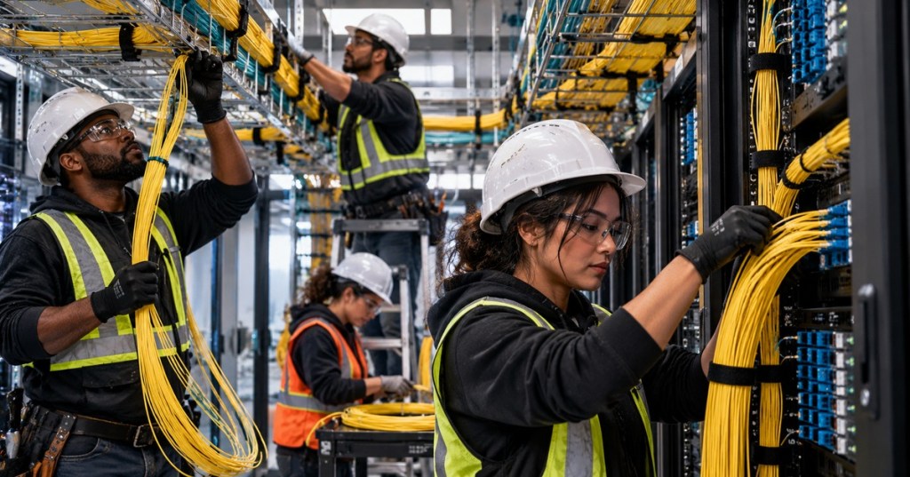
The featured image is original artwork created specifically for OSFOTC.007 and is not reused in the body. The lesson uses a separate original body image and native responsive Gutenberg media embeds.
BitcoinVersus.Tech content is provided for informational and educational purposes.


Leave a Reply