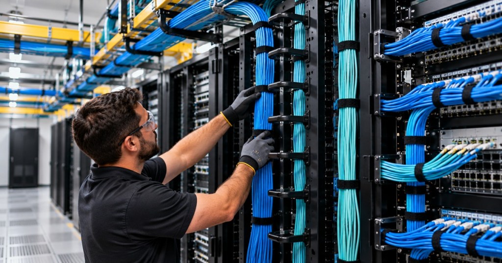
A connector should carry signal. It should not carry the weight of the cable.
That is the basic idea behind cable strain relief: support the cable so gravity, movement, pulling, vibration, and bundle weight are transferred into cable-management hardware instead of into an RJ45 connector, fiber adapter, patch-panel termination, switch port, transceiver, or cable jacket.
This is the next step in the same cabling chain we have been following through bend radius, pulling tension, pathway fill, and service loops. A cable can be routed beautifully and still fail mechanically if nothing is actually supporting it.
Strain Relief Is Mechanical Protection
Every cable experiences mechanical force. Horizontal runs sag between supports. Vertical runs pull downward under their own weight. Patch cords get moved during troubleshooting. Equipment slides forward for service. Bundles shift when another cable is added. Without support, those forces eventually reach the termination.
Good strain relief creates a different load path. The cable’s weight is carried by a J-hook, tray, lacing bar, vertical manager, strain-relief grip, support bracket, cable-management arm, or another approved support. The connector then only has to do the job it was designed to do.
Vertical Fiber Is Where the Rule Becomes Obvious
The Fiber Optic Association’s 2025 installation standard says premises fiber in vertical runs should be supported at frequent intervals to prevent excessive stress on the jacket. FOA specifically notes that service loops, properly applied ties, or strain-relief grip devices can be used as part of the support system.
That matters because a long vertical run can place the weight of many meters of cable on the upper section. If the cable simply hangs from the termination enclosure, the top connector or jacket transition becomes the load-bearing point. The installation may work electrically or optically on day one while accumulating mechanical stress every day afterward.
FOA also warns that supports should be snug without deforming the cable. That distinction is critical. Strain relief that crushes the jacket is not strain relief—it is a different failure mode.
Do Not Let a Switch Port Hold a Cable Bundle
In copper racks, the most common visual mistake is a group of patch cords dropping away from a switch with no nearby support. One patch cord is light. Forty-eight of them are not.
The bundle’s weight can pull downward and sideways on switch jacks, patch-panel ports, and connector latches. This becomes even more important with thicker Cat6 and Cat6A cords or dense patching around high-port-count switches.
Vertical Cable Managers and Lacing Bars Give the Weight Somewhere Else to Go
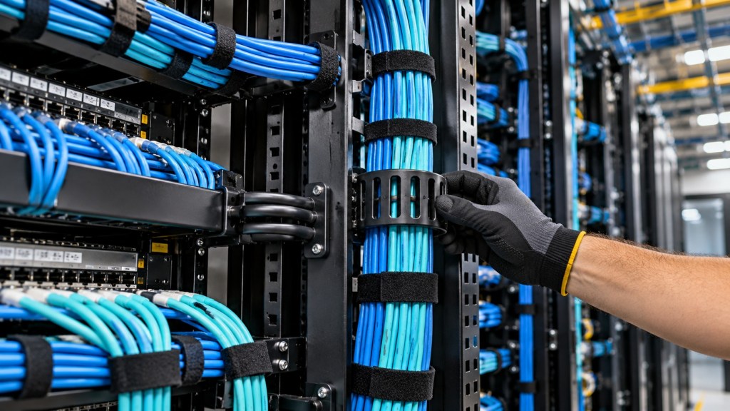
Vertical cable managers, rack fingers, D-rings, and rear lacing bars are not only cosmetic. They create controlled support points so patch cords and trunk cables can change direction without hanging from the equipment face.
A lacing bar behind a patch panel or switch can take the rearward weight of a bundle and create a clean transition toward the vertical manager. A full-height vertical manager can then carry the bundle down the rack while preserving access for server installation and service.
J-Hooks Support the Cable Between the Rack and the Pathway
Outside the rack, cable still needs support. Overhead telecommunications runs often use continuous tray or non-continuous supports such as J-hooks. nVent CADDY’s high-performance J-hooks, for example, are designed for Cat5e, Cat6, Cat6A, Cat7, and fiber and use rounded support surfaces to protect bend radius.
nVent distinguishes between continuous pathways such as cable tray and non-continuous supports such as J-hooks. The purpose is the same: keep the cable from sagging onto ceiling grid, pipes, ductwork, sharp edges, or unrelated equipment while distributing the weight over planned support points.
Support spacing matters too. nVent cites TIA pathway guidance limiting spacing between non-continuous supports to 5 feet, or 1.5 meters, for the applications described in its product documentation. The project specification and currently adopted standard should always control the final installation.
Velcro Is Support Only When It Is Not Crushing the Cable
Hook-and-loop straps are popular because they are reusable, easy to reopen during moves and adds, and less likely than an aggressively tightened plastic tie to deform a communications cable. But even Velcro can be overtightened.
FOA’s installation guidance warns that communications cables are sensitive to compressive loads. Plastic cable ties, especially when tightened with a tool, can create enough pressure to cause attenuation or physical fiber damage. If ties are used, FOA says they should be snug rather than crushing and loose enough to move along the cable by hand.
The principle applies beyond fiber. A perfect-looking bundle squeezed into an oval shape is not professional cable management. The bundle should be controlled, not strangled.
A Service Loop Can Also Become a Support Point
Our service-loop explainer focused on maintenance margin, but FOA notes another use: a properly sized loop can assist with gripping and supporting a vertical fiber cable while also preserving cable for future repair or rerouting.
That does not mean hanging the cable by a tiny coil. The loop still has to meet bend-radius requirements and be attached using hardware appropriate for the cable construction and load.
Cable Management Arms Solve a Different Problem
A server cable-management arm does not primarily support a building cable run. It manages cables that must move with a server as the chassis slides in and out of the rack. The arm controls the bend and travel path so network, management, and power connections do not snag, kink, or get pulled directly at the connector.
That is still strain relief. The mechanical problem is simply dynamic rather than static. A fixed vertical run fights gravity; a cable-management arm controls repeated motion.
Patch Panels Need Rear Support Too
Structured cabling should not arrive at the back of a patch panel as a heavy unsupported bundle. The permanent cable should be dressed, supported, labeled, and given enough slack for retermination without leaving the termination hardware to carry the bundle.
This is one reason proper structured cabling and patch-panel workmanship uses rear managers, support bars, pathways, and controlled bundles. The termination point should be electrically precise and mechanically boring.
Seven Signs the Cable Needs Better Strain Relief
- Patch cords leave a switch and immediately hang downward under their own weight.
- A vertical trunk is supported only at the top and bottom.
- Connectors are visibly angled because the cable is pulling sideways.
- A cable bundle is resting on another server, PDU, pipe, ceiling grid, or sharp rack edge.
- Velcro or cable ties have visibly flattened or deformed the jacket.
- Opening a panel or sliding a server immediately pulls on a connector.
- Moving one cable causes the entire bundle to shift at the ports.
The Field Rule
When looking at any cable, ask one simple question: if I unplugged the connector right now, what would physically hold the cable?
If the answer is “nothing,” the connector may be doing mechanical work it was never designed to do.
Good strain relief is almost invisible because the cable simply stays where it belongs. Weight goes into supports. Movement is controlled. Bend radius is preserved. Ports stay square. Labels remain readable. And the next technician can service the rack without fighting a bundle that is hanging from the equipment.


Leave a comment