Elementary Overview
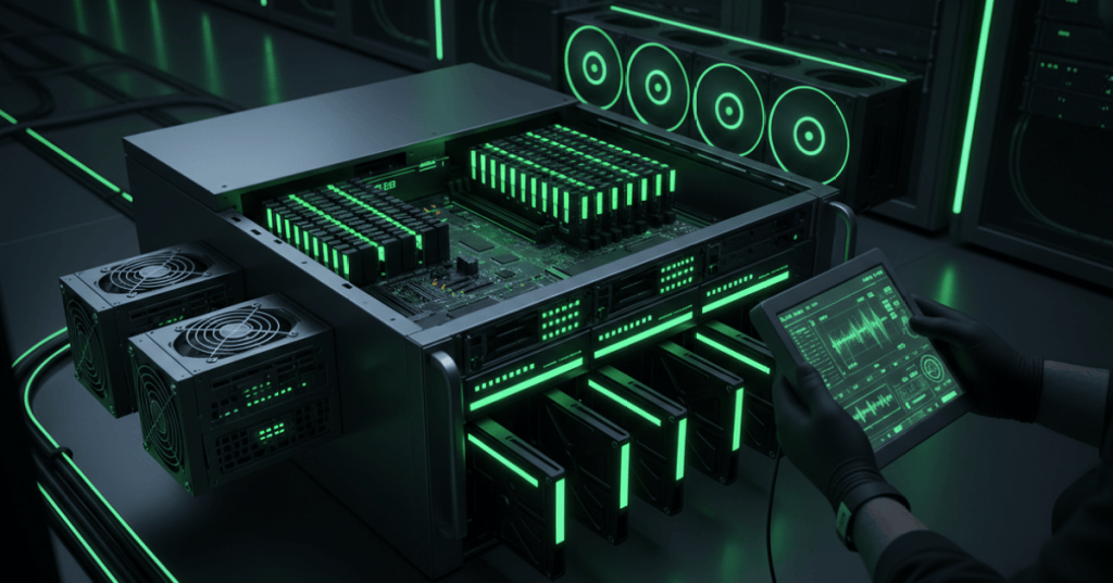
A rack server is a group of replaceable parts working together: processors, DIMMs, storage drives, network interfaces, cooling fans, redundant power supplies, and a management controller. When one part fails, the technician’s job is not to guess. Start with the symptom, read the server’s lights and logs, isolate the smallest likely failure, change one thing at a time, and then prove the machine is healthy again. This lesson continues the physical installation work from OSDCTC.004 by moving from “install the server correctly” to “find the failed component without creating a second problem.”
Read the Evidence Before Opening the Chassis
Begin with the server exactly as it failed. Record front-panel health LEDs, POST messages, fan speed changes, drive indicators, link lights, and the time of the event. Then check the BMC—for example Dell iDRAC, HPE iLO, or another out-of-band controller—for hardware inventory, temperatures, voltage alarms, event logs, and component status. A failed boot does not automatically mean a failed motherboard; a memory training error, missing boot device, PSU fault, or thermal alarm can stop startup earlier. The troubleshooting method from OSITC.001 applies here: identify the symptom, gather evidence, form the smallest testable hypothesis, then make one controlled change.
DIMM and Memory Faults
Server memory faults often appear as POST errors, disabled memory channels, repeated correctable errors, uncorrectable ECC events, or a system that reports less RAM than expected. Before reseating anything, compare the BMC log with the motherboard’s slot labels and the manufacturer’s population rules. Power the system down according to site procedure, use ESD protection, and reseat only the suspected DIMM or follow the approved swap test. If the fault follows the DIMM, the module is the stronger suspect; if the fault stays with the slot or memory channel, investigate the slot, CPU memory controller, or system board instead. Never replace several DIMMs at once unless the work order requires it, because multiple simultaneous changes destroy evidence.
Drive and RAID Faults
A failed drive can be simple, but a degraded RAID set requires care. Read the drive LED state, controller status, slot number, logical-disk condition, and rebuild state before pulling hardware. A technician must distinguish a failed physical drive from a failed cable, backplane, controller path, or merely an empty bay. For hot-swap systems, confirm that the array and platform support live replacement and that the exact failed slot is identified. After replacement, monitor the rebuild instead of assuming the task ended when the new drive’s light turned on. Storage and file-system diagnostics are related but separate: first prove the hardware path is healthy, then diagnose higher software layers if the operating system still cannot use the storage.
Power and Cooling Faults
Redundant power supplies and fans are designed so a server can sometimes stay online after one component fails, but redundancy is not permission to ignore the alarm. Check PSU input, output status, BMC events, rack-PDU source, and whether the remaining supply has enough capacity. Keep the A/B power-path rules from OSDCTC.002 in mind: two PSUs connected to the same failed PDU do not create useful redundancy. A fan alarm should also be treated as a cooling-path problem, not only a fan problem; inspect blocked intake, missing blanks, dust, failed fan modules, and recirculated hot air using the data-center airflow principles already covered in the curriculum.
NIC, Link, and Physical Network Faults
If the server is healthy but has no network connectivity, separate the physical network path into pieces. Check the NIC, link LEDs, transceiver if present, patch cable, patch-panel path, and switch port. A dead link after a server repair can be as simple as a connector that was not fully seated, but it can also be a failed NIC daughter card or PCIe adapter. Use the labeling and verification rules from OSDCTC.003 and avoid changing the server NIC and switch configuration at the same time. Prove Layer 1 first, then move upward to addressing, VLANs, operating-system drivers, and services only after the physical link is known good.
Use a One-Change Fault-Isolation Loop
A strong technician can describe every test as a short loop: symptom → evidence → suspect → one change → verification → documentation. After replacing or reseating a component, boot the server, re-read the BMC event log, confirm that the component appears in inventory, clear only the alarms the procedure allows, and verify that no new fault was introduced. If the original symptom remains, return to the evidence instead of stacking more guesses on top of the first guess. Good documentation should record rack and U position, asset or serial number, failed component, slot, part number, time, test performed, result, and final health state. This creates a troubleshooting history that the next technician can use instead of repeating the same work.
Technician Fault-Isolation Checklist
- Confirm the exact server, rack, U position, hostname, and asset tag.
- Record the original symptom before changing anything.
- Read POST messages, front-panel LEDs, drive LEDs, link lights, and BMC logs.
- Check recent maintenance or configuration changes.
- Identify the smallest likely failed component or path.
- Verify power state and ESD requirements before opening the chassis.
- Change or reseat one component at a time whenever possible.
- Boot and verify inventory, logs, temperature, fans, PSUs, drives, memory, and NIC state.
- Confirm the original service is restored.
- Document the failed part, slot, part number, test, result, and final health state.
Exercises
- A server reports a memory error on DIMM A4. Describe a controlled test that separates a bad DIMM from a bad slot.
- A RAID array is degraded and one drive LED is amber. List the evidence you would record before removing the drive.
- Both server PSUs show no input power. Explain why replacing the PSUs should not be your first action.
- A repaired server boots normally but has no network link. Write a Layer-1 troubleshooting order.
- Explain why changing several components at once makes fault isolation weaker.
- Create a short maintenance note for a server whose failed PSU was replaced successfully.
Knowledge Check + Answers
- What should happen before opening a failed server? Record the symptom and read available LEDs, POST information, and BMC logs.
- What does it suggest if a memory fault follows a DIMM to another approved slot? The DIMM itself becomes the stronger suspect.
- What should be checked before pulling a failed RAID drive? Exact slot identity, array state, controller status, hot-swap support, and rebuild condition.
- Why can two installed PSUs still provide no useful redundancy? They may both be connected to the same power path or PDU.
- What should be proven before troubleshooting IP or VLAN configuration? The physical NIC and network link path.
- What is the core troubleshooting loop? Symptom, evidence, suspect, one change, verification, and documentation.
Elementary Conclusion
Server troubleshooting is easiest when you treat the machine like a set of connected clues. A red light, POST message, BMC log, missing DIMM, degraded drive, failed PSU, or dead NIC is evidence that points toward one part of the system. The safest process is to collect the clues first, change one thing, and then check whether the evidence changed. That keeps the technician from turning one failure into several unknowns. In a data center, the final step matters just as much as the repair: the server must return to a healthy, powered, cooled, connected, monitored, and documented state.
BitcoinVersus.Tech
Advertisement
Editor’s Note:
We volunteer daily to keep the technical information on this platform verifiable. Readers who want to support the research can use the donation information published by BitcoinVersus.Tech.
BitcoinVersus.tech is not a financial advisor. This media platform reports on financial subjects purely for informational purposes.


Leave a comment