Elementary Overview
Ethernet moves network data through copper cable by sending carefully timed electrical signals across twisted wire pairs. A technician does not need to design the signaling electronics, but does need to build the physical path correctly: choose the right cable category, preserve the twists, terminate the conductors in the right order, stay inside the distance limit, and verify the finished link with a tester. The familiar RJ45 connector is the plug most people see, while patch panels and keystone jacks create the permanent cabling behind the rack. This lesson turns those pieces into one technician workflow.
Choose the Cable Category for the Required Link
Cat5e, Cat6, and Cat6A are performance categories for balanced twisted-pair cabling. Cat5e is widely used for 1 Gigabit Ethernet; Cat6 provides tighter performance limits and can support higher speeds over appropriate distances; Cat6A is designed for 10 Gigabit Ethernet over the full standardized channel distance. The technician should match the cable, connector or jack, patch panel, and test limit instead of mixing components casually. For standard structured copper cabling, the familiar maximum channel is 100 meters under the specified conditions, typically built around a 90-meter permanent link plus patch cords. Temperature, patch-cord gauge, installation quality, and category requirements can reduce usable length, so “328 feet” should be treated as an engineering limit, not a promise that every cable run will work at that length.
T568B Defines the Eight-Conductor Order
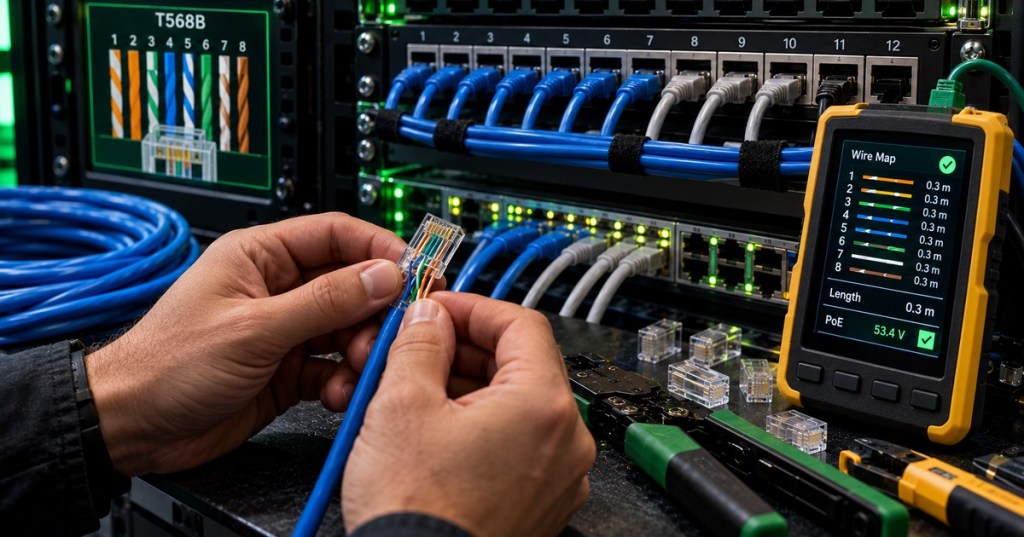
T568B is one of the standardized conductor assignments used on 8-position modular Ethernet terminations. With the plug contacts oriented consistently, the conductor order is white/orange, orange, white/green, blue, white/blue, green, white/brown, brown. T568A is also valid; the critical rule is to follow the site standard and terminate both ends of a normal straight-through channel consistently. The color sequence is not cosmetic. The four twisted pairs are arranged to control electromagnetic coupling and crosstalk, so untwisting the conductors too far near the termination can damage high-frequency performance even when a simple continuity tester reports the pins in the correct order.
Terminate for Mechanical Strength and Signal Integrity
Good termination means more than making the copper touch the contacts. The cable jacket should extend into the strain-relief area, conductors should remain twisted close to the contact point, no copper should be nicked while stripping, and the plug or jack must match the conductor type and cable category. In permanent structured cabling, solid horizontal cable is normally terminated to keystone jacks or patch panels rather than being treated like a long patch cord. Patch panels give technicians a labeled, serviceable transition between the building cable and short patch cords leading to a network switch. Preserve bend radius, avoid crushing the cable with ties, and label both ends before the bundle disappears into a rack.
PoE Adds Power to the Same Copper Pairs
Power over Ethernet (PoE) allows a compatible switch or injector to deliver DC power over the same balanced cabling used for network data. That is useful for access points, cameras, phones, sensors, and other edge devices, but it raises additional installation concerns. The technician should confirm the power source, powered-device requirement, cable category, conductor material, bundle size, and site thermal guidance. Higher current through large cable bundles can create heat, while poor terminations increase resistance and local heating. A working data link therefore does not automatically prove that a cable is suitable for the intended PoE load.
A Wiremap Tester and a Cable Certifier Answer Different Questions
A basic tester can find opens, shorts, reversals, split pairs, and some length problems. That is useful field evidence, but certification equipment goes much deeper. A copper certifier can evaluate parameters such as insertion loss, NEXT (near-end crosstalk), return loss, propagation delay, resistance, and length against a defined category test limit. This distinction matters because a cable can have a perfect pin-to-pin wiremap and still fail at 1G, 2.5G, 5G, or 10G because its high-frequency performance is poor. For installation acceptance, use the test method required by the work order or cabling standard, save the result, and associate it with the exact cable ID. That turns “the cable looks right” into traceable evidence.
Technician Workflow
- Read the work order and confirm endpoint A, endpoint B, cable category, and required test standard.
- Confirm the cable is solid copper where required; do not substitute copper-clad aluminum for standards-based permanent cabling.
- Measure the route and leave service slack without exceeding the allowed channel design.
- Protect minimum bend radius and avoid crushing, kinking, or over-tightening bundles.
- Label both cable ends before termination.
- Terminate to the site standard—commonly T568B—while preserving pair twists.
- Seat the jacket correctly and inspect all contacts or IDC terminations.
- Patch to the correct switch and endpoint ports.
- For PoE circuits, confirm the required power class and switch/injector capability.
- Run wiremap and length testing; run certification when required.
- Save the result against the cable ID and update rack/patch-panel documentation.
- Verify link state on the NIC and switch, then confirm the intended network service.
Worked Example
- Requirement: one 10G copper link from patch panel to server rack.
- Selected system: Cat6A cable, Cat6A jacks/patch panel, Cat6A patch cords.
- Permanent link: 84 m.
- Patch cords: 3 m at the switch and 3 m at the server.
- Total channel: 90 m.
- Wiring: T568B at both terminations.
- Acceptance: wiremap correct, length within limit, Cat6A certification PASS, switch and NIC negotiate the intended link speed.
Exercises
- Write the eight T568B conductor colors in pin order.
- Explain why preserving the twists close to the termination matters even when wiremap is correct.
- A permanent link is 92 m and the two patch cords total 12 m. Calculate the channel length and identify the problem.
- Explain one difference between a continuity/wiremap tester and a standards-based cable certifier.
- List three ways poor cable management can damage Ethernet performance or serviceability.
- Describe why PoE increases the importance of conductor material, termination quality, and bundle temperature.
- Choose Cat5e, Cat6, or Cat6A for a new full-distance 10GBASE-T installation and explain why.
Knowledge Check + Answers
- What is the common maximum structured-cabling channel length? 100 m under the specified channel conditions.
- What is the common permanent-link maximum? 90 m.
- What does T568B specify? The standardized assignment of the eight conductors to the modular connector or jack positions.
- Can a correct wiremap guarantee high-speed Ethernet performance? No. High-frequency loss and crosstalk can still fail.
- What is NEXT? Near-end crosstalk, unwanted coupling measured near the transmitting end.
- Why use a patch panel? It provides an organized, labeled, serviceable termination point for permanent cabling.
- What does PoE add to Ethernet cabling? DC power delivery over the copper pairs in addition to data signaling.
Reference Resources
Elementary Conclusion
A copper Ethernet cable works because eight small wires are arranged as four carefully twisted pairs and connected in the correct order. The technician’s job is to protect that design from one end of the link to the other. Pick the right cable category, follow T568B or the site’s approved pinout, keep the twists intact, stay inside the distance limit, route the cable neatly, and test the result. If PoE is being used, the cable also becomes part of the power system. In simple terms, a good Ethernet cable is not merely eight wires that touch the right pins; it is a controlled electrical path that must carry data—and sometimes power—reliably.
BitcoinVersus.Tech
Advertisement
Editor’s Note:
We volunteer daily to ensure the credibility of the information on this platform is Verifiably True. If you would like to support our research initiatives, please donate here: 3C9o19EH5HSiwEPyCTmEKzxhNCbo2X6TTb
BitcoinVersus.tech is not a financial advisor. This media platform reports on financial subjects purely for informational purposes.


Leave a comment