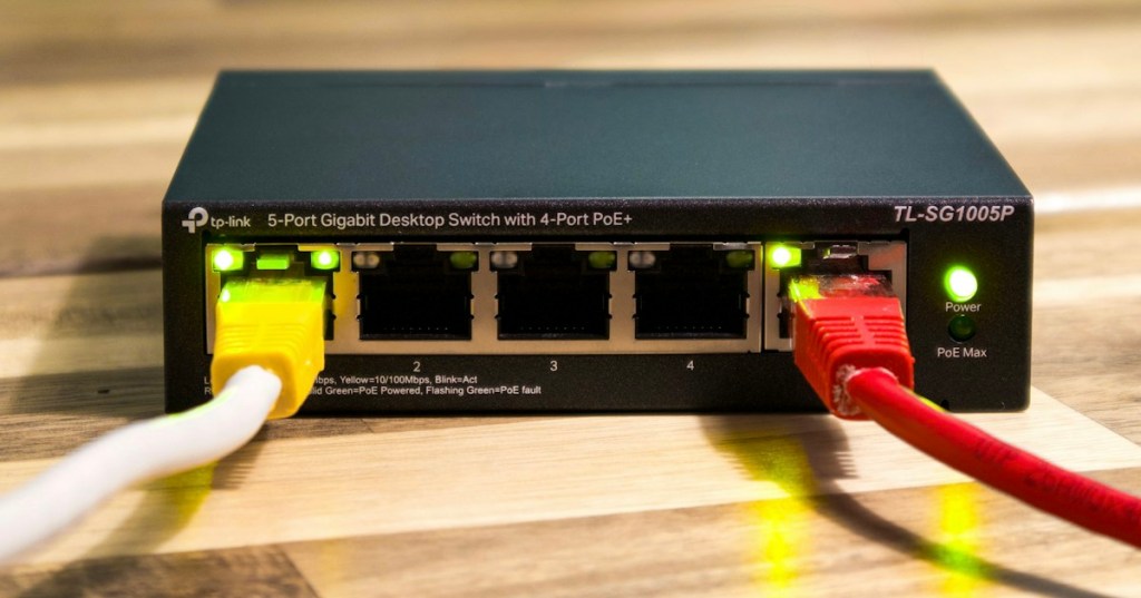
Spanning Tree Protocol (STP) is a Layer 2 protocol that prevents Ethernet switching loops while still allowing redundant physical links to exist. Redundancy is valuable because a backup cable can keep a network online after a failure, but two active Layer 2 paths can also create a loop that repeatedly circulates broadcast and unknown-unicast frames. STP solves that problem by building a loop-free logical topology on top of a physically redundant network.
Why a Layer 2 Loop Is Dangerous
An Ethernet frame does not have the same hop-count protection that an IP packet gets from TTL. If redundant links create a loop between network switches, a broadcast such as an ARP request can be flooded from switch to switch repeatedly. The result can be a broadcast storm, duplicate frames, unstable MAC address tables, high switch CPU load, and eventually a network that becomes nearly unusable.

BPDUs Are the Messages Switches Use to Build the Tree
STP switches exchange Bridge Protocol Data Units (BPDUs). Cisco’s current STP documentation explains that BPDUs carry information including the root bridge ID, path cost to the root, sending bridge ID, interface information, and protocol timers. Switches compare this information and agree on one logical tree. The protocol therefore depends on switches communicating their view of the topology instead of each switch making an isolated forwarding decision.
Cisco’s STP configuration guide describes this BPDU exchange directly, while Juniper’s STP overview describes the same root-election and path-cost process from the RSTP perspective.
The Root Bridge Is the Reference Point
STP elects one switch as the root bridge. The switch with the lowest Bridge ID wins. Bridge ID selection includes bridge priority and a MAC-derived identifier; if priorities are equal, the lower identifier breaks the tie. Every non-root switch then calculates its best path toward that root. In a planned enterprise network, engineers normally want a predictable distribution or core switch to become root instead of leaving the result to chance.
Root, Designated, and Alternate Ports Have Different Jobs
On each non-root switch, the root port is the port with the best path toward the root bridge. On each Ethernet segment, a designated port is selected to forward traffic toward that segment. A redundant port that would create a loop is placed into a non-forwarding role. In Rapid Spanning Tree terminology, an alternate port can remain ready as a backup path. This is the key idea: STP does not physically remove redundancy; it decides which redundant path must temporarily stop forwarding.
Path Cost Decides Which Link Is Better
STP assigns a path cost to links and adds those costs along the path toward the root bridge. Lower total cost is preferred. Faster links generally receive more favorable default costs, although administrators can tune cost when a specific traffic path is desired. Path cost is why a network with several physical routes can still choose one deterministic forwarding path while leaving another route available for failure recovery.
RSTP Converges Faster Than Classic STP
Rapid Spanning Tree Protocol (RSTP) improves recovery after topology changes. Classic IEEE 802.1D STP used slower timer-driven transitions, while RSTP introduced faster negotiation and clearer alternate-path behavior. Modern enterprise switches commonly use RSTP or vendor implementations based on it. The technician still needs the same foundation—root bridge, BPDUs, path cost, and port roles—but should expect modern networks to converge more quickly after a link failure.
STP Works Alongside VLANs and Physical Ethernet
STP lives at Layer 2, so it directly interacts with the Ethernet frames, switch ports, trunks, and VLANs already covered in this course. Depending on platform and mode, a switch may run one spanning tree for the network, separate instances per VLAN, or multiple VLANs mapped into shared spanning-tree instances. Before troubleshooting STP, always confirm that the physical link itself is healthy using the copper-cabling and link-negotiation checks from OSNTC.017 and OSNTC.018.
Basic Technician Verification
When troubleshooting a switched network, verify the topology before changing configuration. On Cisco IOS-style switches, show spanning-tree is the fundamental command. Confirm which switch is root, the local root path cost, each port role and state, and whether topology changes are occurring unexpectedly. If a redundant port is blocking, that can be completely normal. The problem is not that STP blocked a path; the problem is when the tree is different from the intended design or changes repeatedly.
Simple Lab
- Build three switches in a triangle in Cisco Packet Tracer or another lab environment.
- Connect a PC to two different switches so traffic has redundant switch paths available.
- Run
show spanning-treeon each switch. - Identify the root bridge.
- Identify each root port, designated port, and blocking or alternate port.
- Disconnect one active inter-switch link and observe which backup path transitions to forwarding.
- Reconnect the link and watch the topology reconverge.
Knowledge Check + Answers
- Why does STP exist? To prevent Layer 2 switching loops while preserving redundant physical links.
- What is a BPDU? A Bridge Protocol Data Unit used by switches to exchange STP topology information.
- What is the root bridge? The switch elected as the logical reference point for the spanning-tree topology.
- What does a root port do? It is the non-root switch port with the best path toward the root bridge.
- What does a designated port do? It is the forwarding port selected for a Layer 2 segment.
- Why might a healthy port be blocking? STP may intentionally block a redundant path to prevent a loop.
- What is RSTP? Rapid Spanning Tree Protocol, a faster-converging evolution of classic STP.
Elementary Conclusion
The easiest way to remember STP is: keep the backup cable, but block the loop. Switches exchange BPDUs, elect a root bridge, calculate the best paths, forward on the required ports, and hold redundant ports in reserve. If an active path fails, the topology can reconverge and use a backup. For a technician, the first questions are always: Who is root? Which ports are forwarding? Which port is blocked? Did the topology recently change?
Prior Networking Lessons
- OSNTC.012: Network Switch Basics
- OSNTC.016: IPv6 Addressing and Neighbor Discovery
- OSNTC.017: Copper Ethernet Cabling
- OSNTC.018: Ethernet Link Negotiation
Editor’s Note
Featured image: User_Pascal via Unsplash, cropped to exactly 1200×630. Body image: Manuel Luikenga via Unsplash. Technical references include current Cisco and Juniper STP documentation. Every YouTube embed is distinct and directly related to the lesson section it follows. The social-media embed is directly about STP/RSTP field troubleshooting and root/port-role verification.
Support and donation options are available through BitcoinVersus.Tech.
BitcoinVersus.Tech is not a financial advisor. Content is provided for informational and educational purposes.


Leave a comment