
A switch port is the physical and logical connection between an Ethernet switch and a network device. When a workstation, server, access point, or uplink fails, a technician should diagnose the port systematically before changing settings. This lesson follows OSNTC.020: Link Aggregation and LACP and revisits Ethernet Link Negotiation.
LEARNING OBJECTIVES
By the end, identify physical-link faults, distinguish administrative and operational states, interpret switch-interface counters, isolate VLAN and configuration problems, and document a safe corrective action.
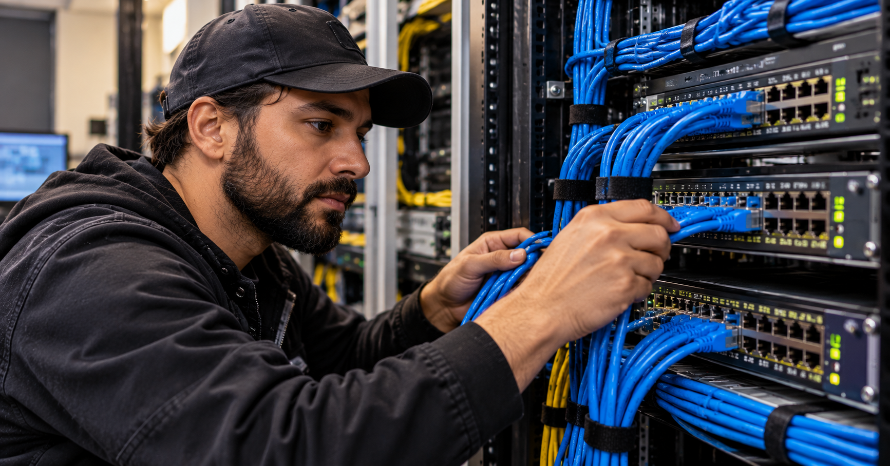
START WITH THE PHYSICAL PATH
Identify both ends of the connection. Verify device power, the patch-cord latch, switch-port LED, patch-panel labeling, and the intended port. Replace a suspect patch cord with a known-good one. Never disconnect an active production uplink without approval. A link LED confirms some physical-layer activity; it does not prove that IP connectivity, VLAN membership, or application traffic works.
READ THE PORT STATUS
On a Cisco IOS-style switch, use the following read-only commands. Exact syntax varies by vendor and operating system.
show interfaces status
show ip interface brief
show interfaces gigabitEthernet 1/0/12
show running-config interface gigabitEthernet 1/0/12
show interfaces counters errors
show logging
A connected or up/up port has an operational link. A notconnect or down/down port suggests an absent or failed link, disconnected device, bad cable, or inactive remote endpoint. Administratively down means the interface has been intentionally disabled. Err-disabled can indicate a protective shutdown; find the underlying cause before re-enabling the port. See Cisco’s switch-port troubleshooting guide for detailed examples.
CHECK SPEED, DUPLEX, AND ERRORS
Compare negotiated speed and duplex at both endpoints. Increasing CRC/FCS errors can suggest physical-layer damage, interference, or other link problems; drops can also arise from congestion. Take two counter readings separated by a controlled interval to distinguish historical counters from a current fault. Do not force speed or duplex without checking the capabilities and configuration of both sides.
Jeremy’s IT Lab demonstrates Cisco switch-interface states, commands, autonegotiation, and error counters.
VERIFY VLAN AND SWITCHING CONFIGURATION
If the link is up but traffic fails, confirm that the access port is in the intended VLAN or that the uplink carries the required VLANs. Check the MAC-address table, the port’s access/trunk mode, and whether a security feature has blocked forwarding. Review OSNTC.004: VLAN Basics and OSNTC.019: Spanning Tree before altering live switch settings.
show vlan brief
show interfaces trunk
show mac address-table interface gigabitEthernet 1/0/12
show spanning-tree interface gigabitEthernet 1/0/12 detail
PRACTICAL TROUBLESHOOTING LAB
In a lab or maintenance window, connect a test PC to a switch. Record the port name, LED state, negotiated speed, duplex, VLAN, and initial error counters. Disconnect the cable and observe the status change. Reconnect it, replace the patch cord, and compare the counters. Finally, confirm the PC receives the expected network configuration and can reach its default gateway. Record evidence before and after each change.
KNOWLEDGE CHECK
1. Does a green link LED prove successful IP connectivity? 2. What does administratively down indicate? 3. Why compare error counters over time? 4. What should you check when a port is up but hosts cannot communicate?
ANSWER GUIDE
1. No: the LED indicates a physical link, not end-to-end service. 2. The interface has been disabled by configuration. 3. To detect actively increasing errors rather than old accumulated values. 4. VLAN assignment, access/trunk configuration, spanning-tree state, port security, addressing, and upstream connectivity.
REFERENCES AND NEXT STEPS
Technical reference: Cisco: Troubleshoot Switch Port and Interface Problems. Video instruction: Jeremy’s IT Lab — Switch Interfaces. Next in the curriculum rotation: Networking Engineering.


Leave a Reply