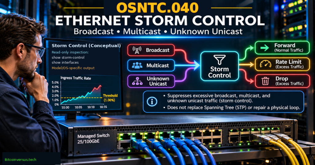
OSNTC.040 teaches how a managed Ethernet switch limits excessive broadcast, multicast, and unknown-unicast traffic without confusing the symptom of a traffic storm with its underlying cause. After OSNTC.039 on Precision Time Protocol, the curriculum turns to Ethernet traffic suppression. The storm-control material also builds on OSNTC.038 on MACsec link protection and builds on OSNTC.019 on Spanning Tree Protocol. Learners will compare the three traffic classes, interpret thresholds in percent, bits per second, and packets per second, and practice reading vendor documentation and fictional counters before proposing any network changes.
Learning Objectives and Prerequisites
- Describe how Ethernet broadcast, multicast, known unicast, and unknown unicast differ.
- Explain the conditions that can produce an excessive Layer 2 traffic rate, including loops, misconfiguration, and abnormal endpoint behavior.
- Distinguish storm control’s ingress traffic suppression from Spanning Tree Protocol’s loop prevention and MACsec’s frame protection.
- Interpret per-port thresholds expressed in percent of link rate, bits per second, or packets per second.
- Identify how Cisco, Arista, and Juniper implementation details and platform limitations can differ.
- Read documented show commands and counters without changing live network configuration.
- Calculate illustrative traffic rates, label units, and identify when percentages conceal packet size or sampling assumptions.
- Document a safe troubleshooting plan, escalation trigger, verification test, and rollback requirement.
Prerequisites: OSNTC.021 on switch-port errors and VLANs, OSNTC.035 on packet capture, and basic knowledge of LLDP neighbor discovery. This is a read-only diagnostic and paper-based lab. Learners must not create broadcast storms, disable Spanning Tree, change switch security settings, or shut down production ports.
Elementary Overview
A switch delivers network frames to their destinations. Some frames are meant for everyone on a local network; others are sent to a group; and some arrive with a destination address the switch has not yet learned. A flood of those frames can consume bandwidth or processing capacity and interfere with normal communication. Storm control is a traffic-limiting feature that can suppress excess traffic on supported switch interfaces.
Think of a switch port as a doorway with a maximum allowed flow for certain types of traffic. If the measured flow exceeds a configured threshold, a supporting switch can drop excess frames or perform another configured action. That does not discover who first generated the extra traffic, nor does it remove a physical cable loop. A technician still has to find the cause.
Why a Storm Happens
Ethernet bridges learn source MAC addresses and forward frames according to the destination MAC address and VLAN. When a destination address is known, a normal unicast frame can be sent toward the learned port. When that destination is unknown, the switch generally floods the frame within the relevant VLAN forwarding domain, excluding the ingress port and subject to applicable safeguards. Broadcast frames are similarly distributed to eligible VLAN ports. Multicast behavior depends on membership-snooping and platform rules.
A Layer 2 forwarding loop can cause copies of certain frames to circulate and multiply. Other causes include faulty applications repeatedly sending broadcasts, misconfigured virtual switches, excessive discovery protocols, or a flood of unknown destinations. Not every elevated broadcast rate proves a loop: a legitimate device-discovery burst may also increase counters. Investigate before attributing intent or declaring an attack.
The Cisco IOS XE storm-control guide describes measured suppression thresholds and actions; the Arista EOS data-transfer guide documents separate inbound broadcast, multicast, and unknown-unicast modes. These are platform-specific implementations, not one command set mandated by Ethernet standards.
Three Traffic Classes to Recognize
- Broadcast: a frame whose destination MAC is the all-ones broadcast address. Normal IPv4 ARP requests are a familiar example of local broadcast traffic; a large repeated stream may overwhelm a VLAN.
- Multicast: a frame addressed to a group destination. Some multicast is essential to legitimate protocols; limiting it too aggressively may interrupt discovery, group traffic, or control-plane communications.
- Unknown unicast: a unicast frame whose destination MAC has not been learned for the relevant VLAN forwarding table. The switch may flood such a frame while learning occurs or when a destination is absent.
A known unicast frame is different from unknown unicast flooding. Some vendor platforms provide a generic unicast control mode and a separate unknown-unicast control mode; others do not. Do not transfer a command named unicast between devices and assume it always means only unknown-unicast traffic. Consult the actual model and software release.
Storm Control and STP Solve Different Problems
Spanning Tree Protocol controls the topology of Ethernet forwarding to prevent a redundant physical path from becoming a persistent Layer 2 loop. Storm control measures traffic arriving on a port and enforces a selected traffic-rate policy when a monitored category exceeds its threshold. They complement one another, but they do not provide interchangeable safeguards.
When storm control starts dropping traffic, the network can appear temporarily stable even if a cable loop or other fault still exists. Removing rate suppression without identifying the cause could re-expose the network to a storm. Similarly, a healthy STP topology cannot prevent every excess multicast or unknown-unicast rate caused by an endpoint. Technicians should correlate storm counters, STP status, interface events, MAC-address movement, and changes to links or topology.
What a Threshold Measures
Vendors may measure a traffic category as a percentage of interface bandwidth, an absolute bits-per-second rate, or packets per second (PPS). They are different units. For an illustrative 10 Gb/s link, a numerical threshold of 1% corresponds to 100 Mb/s as a simple share of nominal link rate. The calculation is an arithmetic conversion, not a recommendation to configure 1% on a real device.
Nominal link speed = 10 Gb/s = 10,000,000,000 bits/s
Illustrative threshold = 1% = 0.01
10,000,000,000 × 0.01 = 100,000,000 bits/s
                           = 100 Mb/s

At 2%: 200 Mb/s
At 0.5%: 50 Mb/s

Numbers represent nominal-rate arithmetic, not
a tested hardware forwarding guarantee.
Percent-based models do not automatically predict packets per second because packet length matters. A large number of small frames can stress forwarding resources at a much lower bit rate than the same number of large frames. Ethernet preamble, interframe gap, VLAN tags, security encapsulation, sampling windows, and ASIC policer implementation can change the relationship between a configured threshold and measured wire utilization.
Arista documents both percentage and PPS thresholds with one-second control intervals in supported EOS versions; it also notes that programmed thresholds may account for Ethernet interframe gaps. Cisco’s current platform guide describes percentage, bit-rate, and—on specified models/releases—PPS modes, with hardware policing and platform-specific restrictions. Arista and Cisco should be consulted separately; the word “storm-control” does not establish cross-vendor compatibility.
Estimate PPS With All Assumptions Visible
As a second training example, imagine 5,000 frames per second averaging 800 counted bytes per frame. Multiplying by eight converts the counted bytes to bits: 5,000 × 800 × 8 = 32,000,000 bits/s, or 32 Mb/s. That value excludes any wire overhead not included in the 800-byte assumption. It is a simple training rate estimate, not a complete Ethernet line-rate measurement.
Sampled rate: 5,000 frames/s
Assumed counted size: 800 bytes/frame
5,000 × 800 = 4,000,000 bytes/s
4,000,000 × 8 = 32,000,000 bits/s
                   = 32 Mb/s before omitted overhead

A different average frame size changes the bit rate
even when frames per second stay at 5,000.
How Devices Enforce a Limit
On supporting switch ASICs, a storm policer may discard excess traffic after a threshold is reached. Cisco also documents interface shutdown or trap actions on applicable models; specific defaults and fallback behavior differ by platform. A shutdown can interrupt healthy services on the same port, so an automated shutdown mode must never be assumed to be a harmless option.
Arista documents storm-control broadcast, multicast, and unknown-unicast modes as independent configurations on physical interfaces, with measurements over one-second intervals. Juniper documents storm-control profiles and, for some switch families, default behavior and interface disable conditions. Neither platform guarantees identical counters, rate units, or shutdown recovery timers to another vendor.
The Juniper storm-control CLI reference notes platform-specific defaults and aggregate-interface behavior, while its show ethernet-switching interfaces reference documents a “storm control in effect” status on certain devices. Treat vendor documentation as scoped to stated hardware and release families.
Read-Only Observation and Vendor Examples
Begin with the organization’s approved monitoring dashboard and vendor-maintained software guide for the exact model. Export or record the current interface state, link rate, relevant traffic counters, STP state, MAC-learning behavior, incident timestamps, and existing storm-control policy without modifying settings. A configuration shown on another switch may be inappropriate for an uplink, voice VLAN, multicast service, or security appliance.
The following read-only examples show vendor command families, not a universal set. Use only commands available in the actual firmware and an account with authorized view access:
Arista EOS (platform / release dependent):
  show storm-control
  show interfaces Ethernet20 counters

Juniper Junos (platform / release dependent):
  show interfaces ge-0/0/0 extensive
  show ethernet-switching interfaces

Cisco IOS XE (check model-specific guide first):
  show interfaces
  show spanning-tree
  show logging
On a Juniper platform, an interface may display a storm-control-specific status after its configured threshold is exceeded, but command output fields and privilege modes vary by version. On Arista EOS, show storm-control reports configured/programmed levels in the relevant software generation. For Cisco, check the supported diagnostic commands and storm-control counters in the exact device family; do not assume every series supports every PPS mode or every interface action.
A Carefully Scoped Configuration Example
To interpret vendor syntax without changing a switch, the following excerpt is an illustrative Arista EOS configuration fragment. Arista documents the forms, but the 1% value here is solely a training input. Do not paste it into live equipment without a peer-reviewed change plan, traffic baseline, rollback procedure, and manufacturer/model verification:
interface Ethernet20
  storm-control broadcast level 1

# Training interpretation only:
# Inbound broadcast rate threshold = 1% of port
# Capacity of a 10 Gb/s link -> nominal 100 Mb/s.
# NOT a universal recommended setting.
The commented lines are explanation, not required Arista configuration. An operational technician should first quantify normal peak bursts and protocol requirements, then evaluate the combined effect of monitoring intervals, threshold mode, and action. Applying an arbitrarily small threshold can discard legitimate DHCP, ARP, multicast or application traffic. Never disable security controls or STP in production merely to make a lab behave as expected.
Tabletop Diagnostic Lab
Use paper, a spreadsheet, or a locally saved text file. The scenario is fictional: interface Ethernet20 connects an access switch to a distribution switch in a 10 Gb/s test network. Alerts report a burst of unknown-unicast and broadcast frames after a topology change. No real traffic generator, cabling change, or network device is involved.
Simulated observation table — NOT live switch output

12:00:00  Link: Up, 10 Gb/s; STP forwarding
12:00:02  Broadcast measured: 40 Mb/s
12:00:03  Broadcast measured: 160 Mb/s
12:00:04  Broadcast measured: 220 Mb/s
12:00:05  Broadcast measured: 45 Mb/s

Hypothetical configured broadcast limit:
1% of nominal 10 Gb/s = 100 Mb/s

Unknown unicast also rose; no verified root cause.
No measured customer impact is provided.
At 12:00:03 and 12:00:04, the simulated broadcast measurements exceed the hypothetical 100 Mb/s threshold. The first and last observations are below it. Those comparisons do not prove which frames the ASIC would actually drop: time alignment, bucket sizes, averaging, counters, and device modes have not been modeled. Nor do they establish that STP failed or that a malicious device is present.
- Identify the first timestamp exceeding the simplified threshold and the maximum reported sample.
- Write a brief incident note distinguishing confirmed measurements from hypotheses such as a cabling loop or MAC-learning anomaly.
- Name three read-only evidence sources that could separate an STP problem from an endpoint-driven flood.
- Identify the service owner, change approver, safety boundary, and stop criterion for any proposed mitigation.
- Describe a validation plan that verifies forwarding and required multicast/broadcast functions before and after an authorized change.
- Explain why a 1% example cannot be adopted as a standard threshold merely because one simulated sample exceeds it.
A strong lab response identifies 12:00:03 as the first overshoot and 220 Mb/s as the highest sample. Suggested read-only evidence includes STP and interface event logs, switch MAC-move statistics, per-class drop counters, topology records, and a permissioned packet capture. The technician should propose—and seek approval for—changes only after defining the affected scope and confirming that service disruption is acceptable.
A Reusable Incident Note and Handoff
Incident ID:
Affected switch / interface / VLAN:
Device model and software release:
Port speed, current link state and STP role:
Observed traffic class and unit:
Measurement interval and peak value:
Existing threshold and action, if confirmed:
Related alerts or topology changes:
Evidence links (redacted as required):
Hypotheses, separately labeled:
Safe next read-only check:
Change owner and required approver:
Rollback and service verification criteria:
Next update time and receiving technician:
A shift handoff should preserve the exact model, software release, measurement units, abnormal time windows, counters, hypotheses and known safe limits. A screenshot of one graph without units or interface identity is rarely enough to justify a switch-wide security change. The technician should avoid asserting that storm control fixed the network when it may have suppressed only one symptom.
Troubleshooting Mistakes and Operational Safety
- Storm control mistaken for STP: rate limiting can suppress traffic without eliminating an Ethernet loop. Review the actual spanning-tree state and topology.
- Percent interpreted as PPS: a rate in packets per second cannot be converted into bits per second without an assumption about frame lengths and accounting overhead.
- Unknown unicast mistaken for all unicast: verify the vendor’s traffic-class definition, since known unicast may be handled separately.
- Multicast controls applied without an inventory: legitimate group applications or protocol control traffic can be disrupted by aggressive thresholds.
- Shutdown action added casually: traffic suppression and interface shutdown are not equivalent; recovering a disabled interface must follow the supported device and change plan.
- Platform-independent commands assumed: configuration syntax, defaults, counters, actions, and sampling differ across Cisco, Arista, Juniper, and hardware generations.
- Fake traffic generated in production: inducing floods risks customer impact and can violate operating policies; use a permitted simulator or a documented offline exercise instead.
- Only an average measured: short bursts or one-second windows may be hidden by multi-minute averages; preserve sampling and counter details.
Assessment and Answer Key
- How do broadcast, multicast, unknown unicast, and known unicast differ?
- Why can a correctly designed storm-control policy still leave the root cause of a network loop unresolved?
- Convert 1% of a nominal 10 Gb/s link into bits per second and megabits per second.
- Estimate the data bit rate for 5,000 frames per second if each counted frame has 800 bytes, excluding other overhead.
- What would a platform-specific storm-control shutdown action change compared with packet suppression?
- In the fictional data, which two timestamps exceed a 100 Mb/s simplified threshold?
- Why is it unsafe to copy one company’s storm-control percentage directly to another network?
- Name at least four fields that should appear in a technician’s incident handoff.
Answers: Broadcast targets the local broadcast domain, multicast a group, unknown unicast an as-yet-unlearned unicast destination, and known unicast a learned destination. Storm control restricts measured traffic rather than repairing its source or topology. One percent of 10 Gb/s is 100,000,000 bits/s or 100 Mb/s. The sample frame data rate is 32 Mb/s before omitted overhead. Shutdown disables forwarding on the affected port and may require a recovery action; packet suppression targets only controlled excess traffic. Simulated overshoots occur at 12:00:03 and 12:00:04. Appropriate thresholds depend on actual traffic and platform semantics. A handoff should specify device, interface, software release, traffic class and units, timestamps, actions, approval owner, and verification plan.
Primary References and Further Reading
- Cisco IOS XE — Flow Control and Storm Control Configuration Guide, modes, platform-specific actions, rate units, and thresholds.
- Arista EOS — Data Transfer: Storm Control, independent broadcast, multicast and unknown-unicast modes, percentage/PPS thresholds.
- Juniper Junos — storm-control statement, profile bindings, platform-specific defaults, aggregate-link details.
- Juniper — show ethernet-switching interfaces, read-only state and storm-control indication.
- Juniper — Example: Using Storm Control to Prevent Network Outages, vendor-specific configuration and verification.
- Arista EOS User Manual, storm-control command reference (technical manual; consult the live HTML guide for version-specific updates).
Elementary Conclusion
Storm control helps a managed switch protect a network against excessive broadcast, multicast, and unknown-unicast traffic. Its limits can be specified in different units, and its actions differ by hardware and software release. The feature can reduce the impact of a traffic storm but cannot by itself fix an Ethernet loop or a faulty endpoint. Successful technicians start with read-only evidence, distinguish facts from hypotheses, verify units and platform behavior, and obtain authorization before making changes to live links.
Editor’s Note: OSNTC.040 follows the published MACsec lesson OSNTC.038 and avoids duplicating the earlier DHCP-snooping/ARP-inspection curriculum. The manufacturer descriptions are derived from Cisco IOS XE, Arista EOS and Juniper primary documentation; software and hardware compatibility require separate checking for each device. The threshold arithmetic and fictional counters were checked, but no real switch, network storm, packet generator, or recovery action was operated. The 1200 × 630 branded cover is a conceptual illustration; its depicted screen text must not be treated as verified or copy-ready configuration. Video identities were checked against public listings. WordPress iframe rendering alone cannot establish that embeds play successfully on desktop or mobile.

We volunteer daily to ensure the information on this platform is Verifiably True. If you would like to support the research, please scan the QR code. Verify the payment destination and amount independently before sending funds.


Leave a Reply