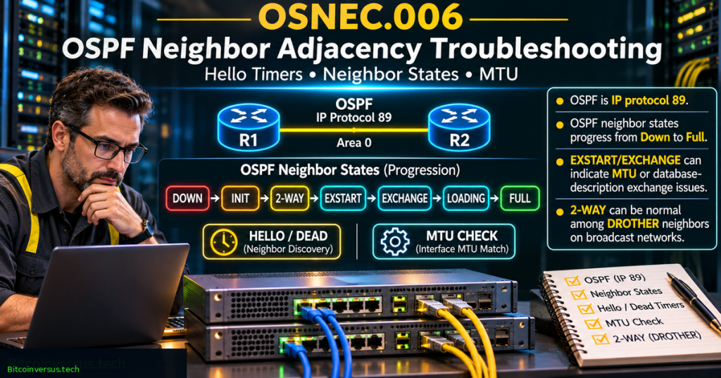
OSNEC.006 teaches how a network engineer diagnoses a failing Open Shortest Path First version 2 (OSPFv2) neighbor relationship. An Ethernet interface may be up while OSPF remains in INIT, EXSTART, EXCHANGE, or LOADING. The engineer must distinguish Hello packet validation, normal designated-router behavior, database-description synchronization, and path MTU problems. The lesson continues OSNEC.005 on LSAs, LSDBs and SPF, focusing on why peers sometimes fail to exchange the topology needed for path calculation.
Learning Objectives and Prerequisites
- Describe the Down, Init, 2-Way, ExStart, Exchange, Loading, Full and special Attempt states.
- Explain why a DROTHER-to-DROTHER neighbor on a broadcast network may legitimately remain 2-Way.
- Check matching area/area-type, Hello and Dead intervals, subnet masks where applicable, unique router IDs, and authentication.
- Recognize a DBD exchange failure and describe how MTU differences can interfere with OSPF adjacency.
- Identify safe read-only Cisco, Arista and Juniper diagnostics and the purpose of IP protocol 89.
- Interpret two fictional fault scenarios without changing production network configuration.
- Prepare an evidence-based handoff with recovery criteria, rollback, and authorized change ownership.
Prerequisites: OSNEC.001 OSPF Fundamentals, OSNEC.004 OSPF Areas and ABRs, and an ability to interpret IPv4 interface details. For capturing evidence, review OSNTC.035 on SPAN and packet capture. The exercises are simulated and read-only; no running router, real OSPF session, routing service, or interface is changed.
Elementary Overview
Think of two routers as people trying to share maps. First they need to hear each other, agree which community they belong to, and recognize their partner. Then they compare map summaries and obtain missing information. A network cable can work while that conversation fails. OSPF neighbor states identify how far the discussion reached, helping engineers select the next piece of evidence rather than guessing.
A neighbor does not always need to reach Full. On an Ethernet segment with a Designated Router (DR) and Backup Designated Router (BDR), two routers that are neither—the DROTHER peers—can remain at 2-Way with each other by design. A point-to-point relationship, in contrast, normally proceeds to Full. Network type and the relevant DR/BDR roles are therefore essential context.
Protocol History and Primary Specification
OSPFv2 is specified by RFC 2328 (April 1998), a standards-track IETF specification for link-state routing with IPv4. OSPF is carried as IP protocol 89, not TCP port 89 or UDP port 89. On ordinary broadcast and physical point-to-point links, the AllSPFRouters multicast address is 224.0.0.5. The DR/BDR exchange uses the AllDRouters address 224.0.0.6 where appropriate. Underlying IP, routing instance, topology and software behavior still matter.
Each OSPF router uses LSAs to describe relevant topology and an LSDB to build its SPF model. A neighbor state problem is about the communication and database exchange needed to sustain that model. Full adjacency is not proof that every expected prefix has been originated or installed into the route table; engineers verify actual routing and forwarding separately.
Neighbor State Machine — From Down to Full
DOWN -> INIT -> 2-WAY -> EXSTART -> EXCHANGE -> LOADING -> FULL

DOWN      No recent accepted Hello from the neighbor
INIT      Hello received; mutual recognition not confirmed
2-WAY     Mutual recognition via Hello neighbor lists
EXSTART   Establish DBD roles and initial sequence numbers
EXCHANGE  Compare link-state database summaries via DBDs
LOADING   Request and receive missing LSAs
FULL      Link-state databases synchronized for adjacency

Exceptions:
- 2-WAY is normal between some DROTHER peers on multiaccess networks.
- ATTEMPT is used with configured NBMA neighbors.
- State can move backward after timeout or sequence failure.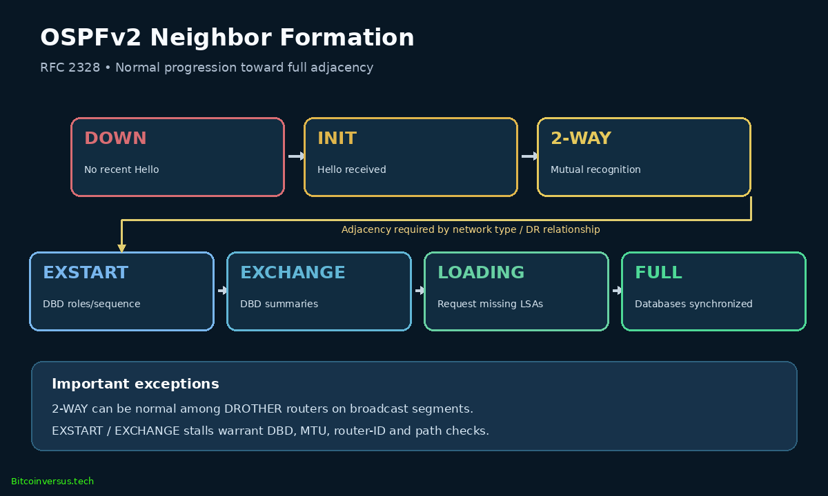
Section 10 of RFC 2328 defines state changes and exception paths. INIT means a Hello was accepted but the router has not confirmed two-way communication. In EXSTART the peers decide the initial database-description sequence; in EXCHANGE they trade summaries. LOADING requests missing LSAs. A neighbor staying at any transitional state for an extended period requires diagnosis, although short transitions during initial startup are normal.
Hello Intervals, Dead Timers and Compatibility
Hello packets advertise HelloInterval, RouterDeadInterval, network mask, router priority, DR and BDR choices, and lists of recently seen peers; their OSPF packet headers carry area and authentication context. RFC 2328 Section 10.5 specifies receive checks: Hello/Dead intervals must match for normal neighbor formation, and advertised network masks are checked except on point-to-point and virtual links. Area and applicable option compatibility, including stub-area E-bit behavior, also matter. Duplicate router IDs can disrupt neighbor identification.
A common example uses 10-second Hellos and a 40-second Dead interval. That pair is not universal to every network type and device. The Dead interval measures time since the last accepted Hello; it is not necessarily the number of seconds from a user-visible incident to service recovery.
Fictional neighbors on one shared segment

             R1           R2
Hello        10 seconds   5 seconds
Dead         40 seconds   20 seconds
Area         0.0.0.0      0.0.0.0

Hello match? 10 = 5   -> No
Dead match?  40 = 20  -> No

RFC 2328 Hello checks reject incompatible intervals.
No production timer changes are authorized by this example.
An engineer should compare both interface settings before proposing a correction. Router priority affects DR eligibility on multiaccess networks and is not itself an ordinary requirement for two neighbors to match. The physical IP mask check has important exceptions on point-to-point and virtual links; a diagnosis that ignores network type can produce incorrect recommendations.
When 2-Way Is Correct
On a broadcast network, an elected DR and BDR reduce the number of full adjacencies. DROTHER peers normally form full adjacencies toward the DR/BDR while remaining 2-Way with one another. A priority of zero prevents a router from being elected DR or BDR but does not automatically prevent adjacency with an elected DR or BDR. On point-to-point interfaces, a persistent 2-Way state is normally not the intended endpoint.
Before classifying a 2-Way listing as a fault, capture router IDs, network type, DR/BDR elections, interface names and the exact relationship being examined. Do not clear neighbors simply to force a state transition. RFC 2328 Sections 9.5 and 10.4 define the applicable relationship rules.
ExStart and Exchange — Database Description and MTU
In EXSTART, neighbors negotiate database-description (DBD) roles and an initial sequence number. In EXCHANGE, they summarize LSDB contents through DBD packets. Persistent EXSTART/EXCHANGE indicates a stalled exchange, not necessarily an area or authentication mismatch. Cisco documents an interface IP MTU mismatch as a common cause: a router may reject a DBD packet whose advertised interface MTU exceeds what it can accept.
Other causes include duplicate router IDs, unexpected sequence numbers, interrupted unicast/multicast delivery, ACL filtering, topology or tunneling faults, and software issues. Cisco documents ip ospf mtu-ignore for exceptional circumstances but recommends investigating mismatched MTUs rather than bypassing the check. Ignoring the check can conceal actual packet-size problems and is not the default repair method. Cisco ExStart/Exchange troubleshooting gives the detailed mechanism.
Loading — Missing LSAs and Retransmissions
A router in LOADING requests link-state records identified during database comparison and not yet held locally. Persistent LOADING can be associated with failed Link-State Requests or Updates, retransmission problems, corrupt records, or resource constraints. Read applicable logs and neighbor-specific LSDB counters before drawing a conclusion. A momentary LOADING state during normal synchronization is not a fault.
Vendor-Aware Read-Only Commands
Use the actual router make, model, release, VRF and management role to select appropriate commands. Cisco IOS/IOS XE, Arista EOS and Juniper Junos expose common OSPF concepts through different operational interfaces. Listed commands are observational; no reset, authentication change or interface reconfiguration is part of the exercise.
Cisco IOS / IOS XE:
  show ip ospf
  show ip ospf neighbor
  show ip ospf neighbor detail
  show ip ospf interface
  show interfaces
  show logging

Arista EOS (check VRF and release):
  show ip ospf neighbor
  show ip ospf neighbor detail
  show ip ospf interface
  show interfaces
  show logging

Juniper Junos:
  show ospf neighbor
  show ospf interface
  show interfaces terse
  show log messages
Cisco’s neighbor troubleshooting guide maps symptoms to CLI observations. Arista EOS documents show ip ospf neighbor with optional VRF detail. Juniper documents show ospf neighbor and interface checks. Use a controlled, permitted capture rather than enabling high-volume debugging on busy production routers.
State-First Diagnostic Checklist
No neighbor / DOWN
  Link, VLAN, interface OSPF, subnet/area, protocol 89,
  unique router IDs, authentication, Hello/Dead settings.

INIT
  Was our Router ID seen in the peer's Hello neighbor list?

2-WAY
  Check broadcast/NBMA network type, DR/BDR and DROTHER.
  A stable two-way relationship may be correct.

EXSTART / EXCHANGE
  Verify actual interface/path MTUs, DBD sequence numbers,
  router IDs, packet delivery and retransmission logs.

LOADING
  Inspect missing LSA requests, updates and acknowledgments.

FULL
  Check route installation and path stability separately.
All findings should be time-bounded. A state observed once during boot is different from a state persisting through repeated checks. Correlate logs, protocol events, interface errors and maintenance records. The state tells an engineer where progress stopped; the evidence determines why.
Hands-On Tabletop — An MTU Discrepancy
The following observations are entirely fictional. R1 and R2 are two intended OSPF point-to-point neighbors. Their interface MTUs differ and database-description sequence events appear repeatedly. The table supports an MTU hypothesis but does not prove that a particular DBD packet was discarded.
Fictional evidence                R1              R2
Interface                         up              up
Area                              0.0.0.0         0.0.0.0
Router ID                         10.255.0.1      10.255.0.2
Hello / Dead                      10 / 40 s       10 / 40 s
Network type                      point-to-point  point-to-point
IP interface MTU                  1500 bytes      9000 bytes
Neighbor state                    EXSTART         EXCHANGE
DBD retransmission indicators     yes             yes
Confirmed cause                   unknown         unknown

No packet capture, live router or actual users exist.- Identify the confirmed MTU difference and explain why MTU incompatibility is plausible.
- List read-only steps to verify the effective MTU through interfaces, VLANs, tunnels and encapsulation.
- Name evidence that could connect a rejected DBD packet to the observed neighbor states.
- Explain why bypassing an MTU check is not the same as fixing forwarding consistency.
- Propose the necessary change owner, approval, rollback and end-to-end verification plan.
Expected reasoning: the advertised interface settings differ by 7,500 bytes; that numerical difference alone is not a measured drop. Examine both effective interfaces and actual DBD exchange before proposing a correction. Restoring Full adjacency is only one verification point; LSDB agreement, route installation and real application forwarding still need confirmation.
Hands-On Tabletop — Two Hello Intervals
For R1 with 10/40-second Hello/Dead values and R2 with 5/20 seconds, RFC 2328 receive rules describe incompatibility. A read-only audit should confirm actual interface and packet values, network type and current state. The numbers are hypothetical; an engineer must not copy the example values to operating equipment. The ratio between 40 and 10 is four, but matching ratio alone is insufficient: the absolute Hello and Dead values must agree.
Operational Safety, Security and Change Control
- Never clear OSPF neighbors, restart the routing process, disable an interface or change MTUs during a learning exercise on a live network.
- Protect routing authentication keys and logs containing sensitive addresses; do not publish secrets in diagrams or GitHub.
- Before a production change, identify impacted prefixes, alternative routes, area boundaries, VRFs and change approvers.
- Retain approved snapshots of current neighbor state, interface MTUs, retransmission logs and related interface counters.
- Define the expected success: stable correct adjacency, consistent topology, correct selected routes, and forwarding checks over an agreed observation period.
- Define rollback and escalation conditions before the change, including what to do if a newly formed adjacency shifts traffic onto an unexpected path.
Engineering Handoff Template
Incident ID / timestamp and time zone:
Device, model, OS version, VRF and interface:
Expected peer address and Router ID:
Observed state, duration and history:
Interface link state, errors, IP and mask:
Area ID, area type and authentication status:
Network type and DR/BDR roles:
Hello / Dead values in seconds:
Interface and path MTU in bytes:
DBD, LSR and retransmission evidence:
What is known / unknown / hypothesized:
Next permitted read-only step:
Change owner, approver, rollback and stop criteria:
LSDB, route and forwarding verification:
Next update time / receiving engineer:
Assessment and Answer Key
- Why is protocol 89 not TCP or UDP port 89?
- List the standard OSPFv2 neighbor-state progression.
- On what type of relationship can 2-Way be a correct final state?
- Which Hello fields must normally agree, and what is the point-to-point mask exception?
- How can MTU cause EXSTART/EXCHANGE problems?
- Does a Full state guarantee every expected route is installed?
- Why do 10/40 and 5/20 values not become compatible merely because both share a 4:1 ratio?
- What belongs in an authorized, evidence-based handoff?
Answer key: OSPFv2 is carried as IP protocol 89; no TCP/UDP port is involved. States are Down, Init, 2-Way, ExStart, Exchange, Loading and Full, with Attempt used for NBMA cases. Two DROTHERs on eligible multiaccess networks may remain 2-Way. Matching Hello/Dead intervals, area and relevant options, security and applicable masks matter; RFC 2328 exempts point-to-point and virtual-link masks from the ordinary Hello receive comparison. An incompatible MTU may stall DBD processing. Full means synchronization of the adjacency, not a guarantee of desired route presence. Timers must match in absolute seconds. A complete handoff includes peer identity, evidence, uncertainties, permissible next checks, approval, rollback and recovery verification.
Fourteen-Point Self-Assessment
0 = missing; 1 = partial; 2 = clear and evidenced
Scoped neighbor, interface and expected state        __/2
State + DR/DROTHER exceptions correctly interpreted  __/2
Timers, area, router IDs, security checked            __/2
MTU/DBD facts distinguished from hypotheses           __/2
Read-only checks chosen, safe action boundaries       __/2
Change approval, rollback, recovery tests defined     __/2
Handoff timestamp, evidence and next owner recorded   __/2
Total                                                 __/14
The rubric evaluates the written reasoning of an educational exercise, not readiness to perform a production router change or an official vendor certification.
Primary References and Further Reading
- IETF RFC 2328 — OSPF Version 2, especially Sections 9 and 10.
- Cisco — Troubleshoot OSPF Neighbor Problems.
- Cisco — ExStart / Exchange Problems and MTU.
- Arista EOS — OSPFv2 Reference.
- Juniper — OSPF Verification and Monitoring.
- Practical Networking — OSPF Hello Packets; Practical Networking — Neighbor States.
Elementary Conclusion
An OSPF neighbor problem can often be narrowed by locating the state transition that failed. Hello parameters and routing identities govern discovery; network type and DR election determine whether a full adjacency is required; and DBD exchange, MTU and LSA synchronization influence ExStart, Exchange and Loading. Reliable engineers gather read-only evidence, keep hypotheses distinct from confirmed facts, and verify forwarding and route installation before declaring recovery.
Editor’s Note: OSNEC.006 follows published OSNEC.005. Protocol details were checked against RFC 2328, Cisco, Arista and Juniper documentation. All router outputs, timers and MTU scenarios are fictional. No actual router command was executed, no routing configuration was changed, and no production recovery was performed. The original 1200 × 630 featured illustration and separate 1200 × 720 technical diagram are branded “Bitcoinversus.tech” in neon green at bottom-left. The two Practical Networking videos are embedded as native Gutenberg video blocks; actual playback and mobile viewport appearance require independent confirmation.

We volunteer daily to ensure the information on this platform is Verifiably True. If you would like to support the research, please scan the QR code. Independently verify the destination and amount before donating.


Leave a Reply