
OSNTC.039 introduces the Precision Time Protocol (PTP), standardized under IEEE 1588, and shows technicians how to assess clock distribution across Ethernet without changing live systems. The lesson follows OSNTC.038 on MACsec Ethernet security: where MACsec protects supported links, PTP supplies timing to compatible devices. Learners will distinguish grandmasters and switch timing roles, examine packet exchanges and hardware timestamps, calculate clock offset, and document a safe diagnostic plan.
Learning Objectives and Prerequisites
- Define a PTP grandmaster, ordinary clock, boundary clock, transparent clock, and timing domain.
- Explain the function of Announce, Sync, Follow_Up, Delay_Req and Delay_Resp messages in the appropriate profile.
- Identify hardware timestamp support and distinguish a NIC physical hardware clock (PHC) from the host system clock.
- Calculate approximate client clock offset and mean path delay with four timestamp values and state the assumptions.
- Compare IEEE 1588 default and IEEE 802.1AS gPTP concepts, including domain, transport, and delay-mechanism compatibility.
- Use read-only commands and management GET queries to gather PTP evidence without adjusting a clock.
- Identify safe escalation steps when a timing source, switch port, or management dataset differs from its intended design.
- Complete a written fault-isolation exercise and answer the end-of-lesson assessment.
Prerequisites: Ethernet switching, LLDP neighbor discovery, 802.1X port authentication, and basic Linux command inspection. The optional arithmetic example requires only Python 3. The networking exercise is observation-only: do not start timing daemons, change security controls, or modify production device clocks.
Elementary Overview
A clock reading on one computer can differ from another even when both appear to show the same time. Applications that coordinate industrial equipment, broadcast frames, distributed measurements, or network events sometimes require more precise agreement than ordinary office timekeeping. PTP uses timestamped messages to let a receiving clock estimate its difference from a selected time source. Its actual accuracy depends on network design, hardware, delay symmetry and clock quality.
Imagine musicians following one conductor. In a PTP domain, the grandmaster is the selected reference. Some network devices simply transport PTP traffic; specialized devices also correct for internal forwarding delays or synchronize to one source while distributing time to other ports. Ethernet link LEDs do not prove the musicians—or network clocks—are synchronized.
History and Current Standards
IEEE 1588 was first issued in 2002 and revised in 2008. IEEE 1588-2019 remains an active major edition with later amendments including IEEE 1588a-2023, which clarified BMCA behavior. The standard supports configurable profiles; compatible profiles and data sets, not just generic PTP capability, determine interoperability. The separate IEEE 802.1AS-2025 standard specifies generalized PTP (gPTP) for time-sensitive networks and supersedes IEEE 802.1AS-2020.
PTP differs from NTP chiefly in its timing models, network roles, and common use of hardware timestamping and timing-aware network equipment. A well-engineered hardware PTP deployment can achieve sub-microsecond synchronization, but no protocol alone guarantees a particular accuracy. For general computer timekeeping, NTP remains useful. Compare the two approaches in the Network Time Foundation’s technical study.
Clock Roles and the Grandmaster Selection Process
- Grandmaster: the preferred source of timing within a PTP domain, potentially referenced to GNSS or an approved oscillator.
- Ordinary clock: one PTP port acting as a timing source or receiver under its selected role.
- Boundary clock: a multiport timing-aware device whose local clock follows an upstream source and serves other PTP ports.
- Transparent clock: measures time a timing packet spends crossing a device and contributes residence-time correction rather than acting as an ordinary downstream source.
- Domain: a logical group of clocks sharing a timing context; a mismatched domain can prevent expected synchronization.
In the default BMCA, clocks compare data from Announce messages and local datasets. Depending on profile, selection criteria include configured priority, clock class, clock accuracy, offsetScaledLogVariance and clock identities. A source is not elected merely because it has the smallest IP address. Changing election settings on production equipment may influence many downstream devices and requires the designated approval.
Four Messages and Four Timestamps
In a common two-step end-to-end (E2E) arrangement, the grandmaster sends Sync and a following Follow_Up carrying the precise transmit timestamp. The client sends Delay_Req; the grandmaster responds with Delay_Resp. Other profiles use one-step timing or peer-delay (Pdelay) messages, so the shown sequence is illustrative rather than universal.
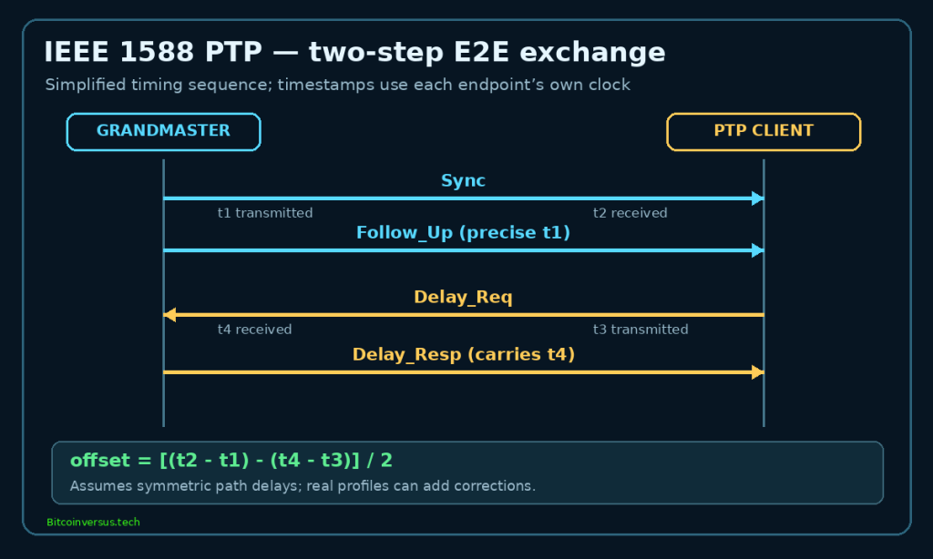
t1 marks the grandmaster sending Sync, t2 the client receiving it, t3 the client sending Delay_Req, and t4 the grandmaster receiving Delay_Req. The client combines the timestamp pairs to estimate offset and path delay. With symmetric forward/reverse path delays and no unmodeled corrections, the simplified formulas are:
forward = t2 - t1
reverse = t4 - t3
offset_client_minus_source = (forward - reverse) / 2
mean_path_delay = (forward + reverse) / 2
Consider fictional values measured in nanoseconds by the clocks at the appropriate endpoints:
t1 = 1,000,000,000 ns (source clock)
t2 = 1,000,001,600 ns (client clock)
t3 = 1,000,020,000 ns (client clock)
t4 = 1,000,021,400 ns (source clock)

forward = 1,600 ns
reverse = 1,400 ns
offset = (1600 - 1400) / 2 = +100 ns
mean path delay = (1600 + 1400) / 2 = 1,500 ns
The positive +100 ns result means the client clock is ahead of the reference under the stated sign convention. One example measurement does not prove sustained precision, and physical path asymmetry can bias the result even if the formulas are applied perfectly. Hardware timestamp uncertainty, network residence-time corrections, oscillator drift, queueing and synchronization-servo behavior must also be considered.
Hardware Timestamps and Two Different Clocks
A software timestamp is taken by the host networking stack, where scheduling and packet handling can add variable delay. A hardware timestamp can be captured nearer the actual transmit or receive event at a network interface controller (NIC). Linux exposes certain PTP-capable NIC clocks as physical hardware clocks (PHCs), commonly represented by devices such as /dev/ptp0. Capability depends on NIC, driver, firmware and kernel support.
In a common deployment, ptp4l disciplines a PHC from PTP network messages; phc2sys may then synchronize the Linux CLOCK_REALTIME system clock from the PHC. Those are separate synchronization relationships. A stable PTP port and low reported offset do not prove that applications reading the system clock have accurate UTC time. The linuxptp phc2sys manual documents time-scale issues, including the potential offset between continuous PTP time and UTC. Starting or reconfiguring either timing daemon can change clock state and must be authorized.
Transport, Domains, and Compatibility
Depending on the profile, IEEE 1588 packets can use native Layer 2 Ethernet or UDP over IPv4/IPv6. With UDP, destination port 319 carries event messages and 320 carries general messages. Direct Layer 2 PTP uses EtherType 0x88F7. Vendor implementations differ; Cisco Nexus PTP documentation provides transport and feature restrictions for a particular NX-OS family rather than every switch model.
A timing network must also agree on its profile, PTP domain, delay mechanism (end-to-end versus peer-to-peer), message intervals, source roles and configured addressing. A switch may forward ordinary Ethernet while rejecting or not receiving the needed timing messages. VLAN membership, multicast filtering, ACL policy, asymmetric paths and unsupported one-step/two-step modes can contribute. Review OSNTC.022 on VLAN tagging when mapping timing traffic.
A Read-Only LinuxPTP Inspection Procedure
The following commands inspect an already managed and authorized Linux machine. Substitute its actual interface for eno1. The pmc GET queries require access to the existing local ptp4l management socket; without a running daemon or permissions, they may return an error or no response. None of the examples starts a daemon, changes a network interface, resets a clock or issues a management SET command.
ip -br link show
ethtool -T eno1
ps -eo pid,args | grep '[p]tp4l'
ps -eo pid,args | grep '[p]hc2sys'
pmc -u -b 0 'GET DEFAULT_DATA_SET' 'GET PARENT_DATA_SET'
pmc -u -b 0 'GET CURRENT_DATA_SET' 'GET PORT_DATA_SET'
An operator can inspect the grandmaster identity, domain, current data set, port state, meanPathDelay, reported offset and timestamping support. Management field names vary with standards edition and software. For an existing local ptp4l process, pmc -u selects the Unix-domain socket transport; -b 0 controls boundary hops. Only GET requests are used. Refer to the primary pmc(8) and ptp4l(8) documentation before using a real interface.
ethtool -T reports capability, not whether the NIC is currently timestamping PTP packets correctly. ps process presence is not proof of successful clock convergence. The port may be in a timing-receiver state and still fail a required accuracy objective. A healthy system needs an agreed reference source, sufficient observation period, and a valid independent measurement method.
Paper Lab: Diagnose a Profile Mismatch
Examine three entirely fictional endpoints with physical links up. Do not alter any device during the exercise:
Node A: domain 24 | UDPv4 | E2E delay | hardware timestamps
Node B: domain 24 | UDPv4 | E2E delay | hardware timestamps
Node C: domain 0  | L2 Ethernet | P2P delay | software timestamps

All three ports show an Ethernet link.
No evidence is available about signed-off timing architecture.
Node C differs from A and B in domain number, transport, delay mechanism and timestamp source. The proper first task is to confirm the approved network timing profile and intended topology, not to assume a damaged cable or force the same settings across every switch. The technician should document differences, identify the design owner, collect relevant read-only counters and request authorized changes only after compatibility is established.
Paper Lab: Interpret Offset Samples
FICTIONAL DATA — not actual pmc or device output
portState: CLIENT
grandmasterIdentity: 00:1b:19:ff:fe:23:45:67
meanPathDelay: 1500 ns
offsetFromMaster samples (ns): +210, +140, +80, +50, +30
PHC device: /dev/ptp0
System-clock UTC verification: not supplied
Offset magnitudes decline across the five invented samples. That is consistent with improvement in the selected trace, but five values cannot demonstrate stability, accuracy, holdover performance or compliance with a professional profile. The snapshot does not report sampling interval, reference uncertainty, environmental drift, jitter distribution, independent time comparison, or asymmetry. Nor does it prove that the operating-system time is synchronized. Treat observed state and guaranteed performance as separate claims.
Optional Local Arithmetic Self-Test
The four-timestamp calculation is reproducible with a short Python 3 program that needs no network access or hardware. Two assertions check the expected values; this is a test of illustrative arithmetic, not a test of the physical PTP protocol:
t1 = 1_000_000_000
t2 = 1_000_001_600
t3 = 1_000_020_000
t4 = 1_000_021_400
forward = t2 - t1
reverse = t4 - t3
offset_ns = (forward - reverse) / 2
delay_ns = (forward + reverse) / 2
assert offset_ns == 100
assert delay_ns == 1500
print(f"offset={offset_ns:.0f} ns delay={delay_ns:.0f} ns")
The authoring environment executed those arithmetic assertions successfully; the result was offset=100 ns delay=1500 ns. No PTP grandmaster, NIC PHC, or linuxptp daemon was exercised as part of that Python check.
Troubleshooting and Escalation Checklist
- Wrong grandmaster: inspect received Announce datasets, priority, clockClass, clockAccuracy, configured source preferences and approved failover architecture.
- No synchronization despite link up: check domain, profile, addressing, UDP 319/320 or EtherType 0x88F7 as applicable, VLANs, multicast and authorization policy.
- High or changing offset: investigate hardware timestamp availability, packet queueing, correction fields, switch residence time, link asymmetry, oscillators and servo status.
- PHC synchronized but system time wrong: distinguish the PHC from CLOCK_REALTIME, then inspect the authorized phc2sys and UTC offset design without starting a second conflicting clock synchronizer.
- Clock failure during failover: inspect alternate grandmaster quality, selected priority, GNSS/source alarms, holdover performance and profile compatibility.
- Security policy blocks timing: verify Layer 2 controls, OSNTC.030 switch security, approved ACLs and the prior MACsec deployment; do not disable controls to force packets through.
- Hardware unsupported: compare NIC and switch model, PHY, driver, firmware, optics and software against current vendor support documentation.
- Outdated terminology: identify actual source/receiver roles even if a tool uses historical “master/slave” instead of “server/client” language.
Operational Security and Safety
Accurate time can matter for authentication, event ordering, databases, industrial controls, network automation and forensic evidence. A rogue or failing grandmaster can propagate bad time to many devices, while an improperly disciplined system clock may step unexpectedly. IEEE 1588 provides security-related provisions but does not automatically authenticate every permitted timing endpoint. Follow the local source-trust design, network admission controls, management access restrictions and approved monitoring.
Do not start ptp4l or phc2sys, reset clocks, change VLANs, disable MACsec, adjust BMCA priorities, or reconfigure a production time server merely to reproduce a lesson. Escalate to the designated network/timing owner and use a change plan with rollback and independently measured acceptance criteria. Suspicious time-source behavior may also require cybersecurity escalation.
Knowledge Check
- Why can ordinary Ethernet traffic pass while the receiving node fails to synchronize over PTP?
- How does a boundary clock differ from a transparent clock?
- Identify t1, t2, t3, and t4 and calculate offset and mean delay from the example.
- Which ports carry UDP PTP event and general messages? What EtherType identifies direct Layer 2 PTP?
- Why does a PTP-capable NIC not prove that Linux CLOCK_REALTIME is synchronized?
- List each difference between synthetic node C and nodes A/B, and choose a read-only first diagnostic.
- What evidence would you need before claiming sub-microsecond accuracy from reported samples?
- Which timing and security operations require explicit approval?
Answer key: Profile, domain, network transport, filtering, timing mode, or unsupported hardware can prevent synchronization even when Ethernet link is healthy. A boundary clock follows a source and serves downstream ports; a transparent clock corrects residence time. The example gives +100 ns client offset and 1,500 ns mean path delay under symmetry. UDP ports 319 and 320 carry event and general messages, while direct Ethernet PTP uses 0x88F7. PHC synchronization and CLOCK_REALTIME are distinct. Node C differs in domain, transport, E2E/P2P delay and timestamping method. A measured accuracy claim requires sufficient observations, an independently valid reference, jitter and asymmetry analysis, and accepted performance criteria. Clock service changes, source priorities, interface/security settings and service restarts are controlled actions.
Primary Sources and Further Reading
- IEEE 1588-2019 — Precision Clock Synchronization.
- IEEE 1588a-2023 — BMCA Clarifications.
- IEEE 802.1AS-2025 — Timing for Time-Sensitive Applications.
- linuxptp — ptp4l(8).
- linuxptp — pmc(8) PTP Management Client.
- linuxptp — phc2sys(8) and Timescale Usage.
- Cisco — PTP Configuration and Transport.
- Network Time Foundation — PTP and NTP Comparison.
Elementary Conclusion
IEEE 1588 PTP is a structured way to distribute accurate timing among compatible networked clocks. A technician needs to recognize the grandmaster and clock roles, follow the timestamp-message exchange, verify the required profile and domain, and inspect both hardware clock and system clock state. Safe diagnostics separate read-only evidence collection from potentially disruptive clock adjustments. Real accuracy is demonstrated by measurement and design validation, not by a protocol label or a green link LED.
Editor’s Note: OSNTC.039 follows published OSNTC.038 and cites IEEE, linuxptp and Cisco primary documentation checked November 8, 2026; IEEE 802.1AS-2025 supersedes IEEE 802.1AS-2020. All network inventories, identities, offset samples and hardware scenarios are fictional educational data. Python arithmetic assertions were executed locally; live PTP, NIC and managed-switch measurements were not performed. The original 1200 × 630 cover and separate 1200 × 720 diagram include the required bottom-left Bitcoinversus.tech signature. Both YouTube identities were found in public listings; successful playback and responsive visual appearance remain independent QA checks.

We volunteer daily to ensure the information on this platform is Verifiably True. If you would like to support the research, please scan the QR code. Confirm the address and amount with your wallet before sending funds.


Leave a Reply