Elementary Overview
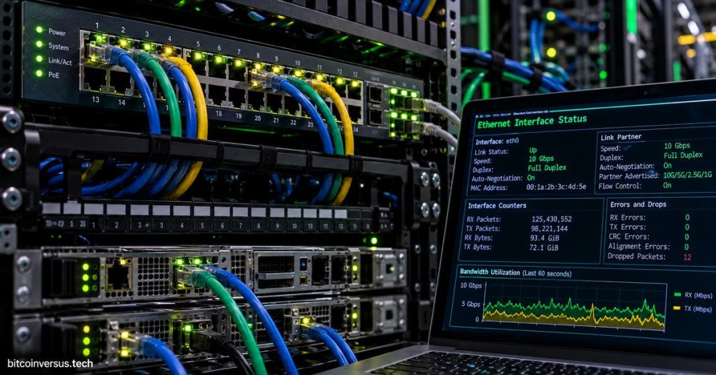
A copper Ethernet cable can be wired correctly and still fail to produce the link a technician expects. After the physical path from OSNTC.017: Copper Ethernet Cabling is installed, the network interface card (NIC) and switch port must establish link, agree on compatible operating parameters, and pass frames without excessive errors. The technician’s job is to verify four things in order: physical link, negotiated speed, duplex mode, and interface health. A green link light is useful evidence, but it does not prove that the link negotiated the intended speed or that the connection is error-free.
Start With Link State and Link LEDs
The first question is whether the two Ethernet PHYs detect one another and establish link. Link and activity LEDs on a NIC, server, switch, or router provide fast physical-layer evidence, although colors and blink patterns are vendor-specific and must be interpreted from the equipment documentation. No link usually points the technician toward the cable path, connector seating, disabled port, incompatible transceiver or media, failed NIC, failed switch port, or power problem before any ARP, IP-address, DNS, or application troubleshooting begins. On copper networks, also verify the RJ45 termination and patch path rather than assuming an illuminated rack means every port is connected correctly.
Speed and Duplex Describe How the Link Operates
Link speed is the signaling rate selected for the Ethernet connection, such as 100 Mb/s, 1 Gb/s, 2.5 Gb/s, 5 Gb/s, or 10 Gb/s when supported by both endpoints and the installed cabling. Full duplex allows both ends to transmit and receive at the same time and is the normal operating mode on modern switched Ethernet. Half duplex is an older shared-medium behavior associated with collision handling and should not appear unexpectedly on a modern point-to-point switched link. A link that comes up at 100 Mb/s when a 1 Gb/s or 10 Gb/s service was expected is a troubleshooting clue: inspect the cable, pair continuity, category, NIC capability, switch-port capability, configuration, and intermediate patching before treating the reduced speed as normal.
Auto-Negotiation Should Usually Be Allowed to Work
Auto-negotiation lets two compatible Ethernet devices advertise supported capabilities and select a common operating mode. In normal modern deployments, leaving both sides on automatic settings is usually safer than manually forcing one side. A classic failure occurs when one endpoint is manually configured while the other is left to infer or negotiate what it can, producing a duplex mismatch or another incompatible condition. The link may remain up while throughput collapses, retransmissions rise, and interface counters reveal collisions or frame errors. If policy requires manual speed or duplex, coordinate the configuration at both ends and document it; do not change only one side as a trial and leave the mismatch in service.
Interface Counters Reveal Links That Are Up but Unhealthy
A technician should record interface counters before and after a test instead of treating every nonzero counter as an active fault. CRC/FCS errors indicate frames that failed integrity checking and can point toward physical signaling problems, damaged cabling, bad terminations, electromagnetic interference, or failing hardware. Collisions or late collisions on a modern full-duplex switch link are abnormal and can suggest a duplex problem or another configuration fault. Input errors, output errors, discards, and drops require context because vendors count them differently, but a counter that rises rapidly while traffic is tested is stronger evidence than an old static number. The correct workflow is to correlate counters with the cable path, negotiated mode, traffic level, and symptoms rather than replacing hardware from one isolated statistic.
Useful Technician Commands
# Linux
ip link show
ethtool eth0
ip -s link show eth0

# Windows PowerShell
Get-NetAdapter
Get-NetAdapter | Format-Table Name, Status, LinkSpeed
Get-NetAdapterStatistics

# Cisco-style switch examples
show interfaces status
show interfaces gigabitEthernet 1/0/1
show interfaces counters errors- Linux: verify administrative state, carrier/link, negotiated speed and duplex, and packet/error counters.
- Windows: verify adapter status, reported link speed, and adapter statistics.
- Managed switch: verify port status, VLAN assignment where relevant, negotiated speed/duplex, and changing error counters.
- Documentation: record the exact interface name, switch port, expected speed, actual speed, duplex, cable ID, and counter values before changing anything.
Technician Troubleshooting Workflow
- Confirm the correct endpoint and switch port from labels or rack documentation.
- Check link LEDs on both ends.
- Reseat the patch cable and verify the correct patch-panel path.
- Confirm the port is administratively enabled.
- Read the negotiated speed and duplex on both endpoints.
- Compare actual speed with the service requirement and the capability of the cable, NIC, and switch.
- Check whether both sides are using auto-negotiation or whether both were intentionally hard-coded.
- Capture interface counters.
- Run a controlled traffic or connectivity test.
- Capture counters again and look for rapidly increasing CRC/FCS errors, collisions, drops, or other faults.
- Swap one known-good component at a time—patch cord, switch port, or endpoint—so the evidence remains traceable.
- If PoE is involved, verify that power delivery and data-link negotiation are both healthy; one can fail independently of the other.
- Restore the approved configuration and document the final negotiated state.
Worked Example
- Expected service: 1 Gb/s full duplex from server NIC to access switch.
- Observed: link LED is on, but the NIC reports 100 Mb/s full duplex.
- Initial counters: no CRC errors.
- Action 1: verify both ends are set to auto-negotiation.
- Action 2: inspect the patch path and replace the server patch cord with a known-good cable.
- Result: link renegotiates at 1 Gb/s full duplex.
- Conclusion: the original patch cord allowed link but did not support the expected Gigabit Ethernet operation reliably. Document the failed cable and remove it from service rather than forcing the port speed.
Exercises
- A server and switch are both Gigabit-capable, but the link shows 100 Mb/s. List five checks to perform before replacing the NIC.
- Explain why a link LED does not prove the connection is operating at the intended speed.
- Describe the difference between link speed and duplex mode.
- Explain why forcing one endpoint to full duplex while leaving the other side mismatched can create severe performance problems.
- A CRC counter rises from 4 to 2,400 during a five-minute traffic test. What does the change tell you that the original value of 4 did not?
- Write the Linux command that displays common speed, duplex, and auto-negotiation details for
eth0. - Write the Windows PowerShell command that lists adapters and their reported link speeds.
Knowledge Check + Answers
- What is the first thing to verify? Physical link state between the two Ethernet endpoints.
- What is normal duplex on modern switched Ethernet? Full duplex.
- What does auto-negotiation do? It lets compatible endpoints advertise capabilities and select a common Ethernet operating mode.
- Does an illuminated link LED prove 1 Gb/s or 10 Gb/s operation? No. It proves basic link state, not the intended negotiated speed.
- What can rapidly increasing CRC/FCS errors indicate? A physical signaling, cabling, termination, interference, or hardware problem.
- Why compare counters before and after a test? To distinguish old historical errors from errors that are actively increasing during the current fault.
- What is the preferred first configuration for speed and duplex in most modern Ethernet links? Compatible automatic negotiation on both ends unless a documented design requires otherwise.
Reference Resources
- Cisco — Troubleshooting Cisco Catalyst Switches to NIC Compatibility Issues
- Linux manual — ethtool
- Microsoft Learn — Get-NetAdapter
- OSNTC.017 — Copper Ethernet Cabling
- OSNTC.011 — Network Interface Card Basics
- OSNTC.012 — Network Switch Basics
Elementary Conclusion
An Ethernet connection is healthy only when more than the light turns on. The cable must create link, the NIC and switch must agree on a useful speed and duplex mode, and the interface must pass frames without a growing pattern of errors. A technician therefore moves from the simplest evidence to the deeper evidence: link light, negotiated speed, duplex, configuration, and counters. If the link is slower than expected or error counters climb during testing, the fault can often be isolated by comparing both ends and changing one component at a time. The central idea is simple: “link up” means the devices can see each other; it does not automatically mean the Ethernet link is operating correctly.
BitcoinVersus.Tech
Editor’s Note:
We volunteer daily to ensure the credibility of the information on this platform is Verifiably True. If you would like to support our research initiatives, please donate here: 3C9o19EH5HSiwEPyCTmEKzxhNCbo2X6TTb
BitcoinVersus.tech is not a financial advisor. This media platform reports on financial subjects purely for informational purposes.


Leave a comment