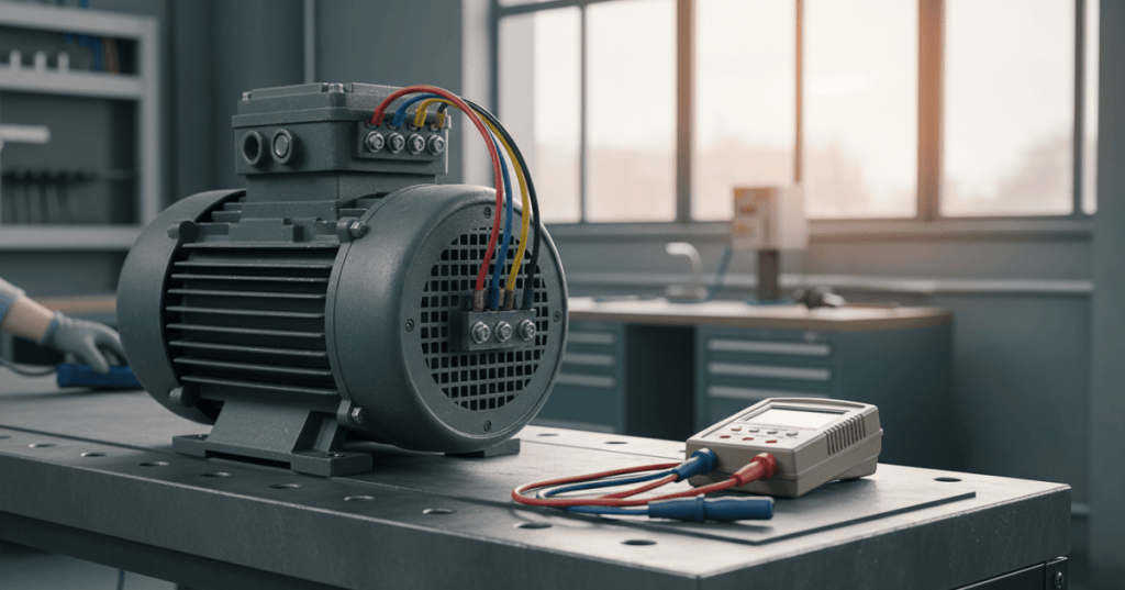
Three-phase power has more than a voltage magnitude: the three alternating waveforms reach their corresponding peaks in an ordered sequence. A three-phase induction motor relies on that order to establish the direction of its rotating magnetic field. Reversed connections may leave all three line-to-line voltages apparently normal while a pump, fan, conveyor or compressor attempts to run backward. Phase sequence verification is therefore a separate commissioning check from ordinary voltage and current balance.
OSETC.041 advances the Electrical Technician curriculum after OSETC.040 — Three-Phase Motor Voltage Imbalance, OSETC.039 — Three-Phase Motor Current Imbalance, and OSETC.038 — Motor Winding Resistance. The preceding lessons teach whether the electrical supply and motor phases are healthy; the new chapter teaches whether phase order matches the equipment’s intended rotation.
Learning Objectives and Prerequisites
- Define phase sequence, phase rotation, rotating field and mechanical shaft direction without treating them as interchangeable measurements.
- Explain why exchanging any two phases reverses the rotating field in a conventional line-fed three-phase induction motor.
- Distinguish a live-line phase sequence indicator from an instrument designed to predict an isolated motor’s rotation.
- Calculate synchronous speed for a motor with a specified number of poles and supply frequency.
- Explain what a tester’s clockwise or counterclockwise indicator actually says about its connected lead order.
- Create a safe phase-sequence verification record without manipulating an energized installation or running a motor unexpectedly.
- Recognize important exceptions for variable-frequency drives, bypass circuits, mechanical transmissions and manufacturer-specific requirements.
Prerequisites: the distinction between line and phase, a basic knowledge of the three-phase supply waveforms, motor nameplate interpretation and authorization requirements for industrial electrical work. The lesson teaches concepts, evidence interpretation and safe planning. It does not authorize unqualified personnel to probe energized conductors, change wiring or perform a motor bump test.
The Physical Meaning of Phase Sequence
In a balanced three-phase system, sinusoidal phase quantities have nominally equal magnitude and are displaced by 120 electrical degrees. One sequence may be denoted A–B–C or L1–L2–L3; reversing two positions produces the opposite order, such as A–C–B. The exact designation depends on the measurement convention and on which physical terminal a tester identifies as L1.
The electromagnetic field produced by a three-phase stator advances around the motor as the excitation sequence moves through its windings. Changing the sequence reverses the field’s direction. For the ordinary induction motor directly connected to a fixed-frequency supply, the rotor follows the field’s direction at a speed somewhat below synchronous speed while loaded.
For a mathematical model of an ideal balanced phase set, the instantaneous phase-to-reference voltages may be represented as follows. The expressions describe a conceptual signal; they are not captured measurements:
vA(t) = Vm × sin(ωt)
vB(t) = Vm × sin(ωt − 120°)
vC(t) = Vm × sin(ωt + 120°)
ω = 2πf
If B and C trade positions relative to the connected stator terminals, the excitation order reverses. The three phases can retain equal RMS magnitudes, so a technician cannot verify rotation solely by observing that all line-to-line voltages are near nominal. The physical terminal order and relevant equipment drawings are essential.
Fluke Corporation, “How to Measure Phase Rotation with the Fluke T+ Pro | 3-Phase Electrical Testing Explained” (January 27, 2025). The official vendor demonstration explains the tester’s phase indication and illustrates the importance of a consistent lead-connection convention. Demonstration is educational, not permission to perform energized work without qualifications and controls.
Line Phase Sequence Is Not Guaranteed Shaft Direction
A phase-sequence indicator reports the order of three observed line conductors relative to its own probe assignments. It does not, by itself, establish that a particular pump’s impeller will turn in the required direction. Motor terminal mapping, internal connection scheme, any intervening drive, mechanical gearing and the equipment’s marked direction all matter.
A separate motor-rotation tester may determine intended motor terminal relationships without energizing the motor. Megger describes that distinction in its Motor and Phase Rotation Tester product documentation. Such functions differ by instrument: a simple mains phase-sequence indicator is not automatically a powerless motor-rotation test set.
Fluke’s 9040 Phase Rotation Indicator manual explains that its clockwise/counterclockwise light refers to the instrument’s observed rotary field after connecting three leads. It also warns about misleading indications under some erroneous connections. Confirm all three test points, the model’s stated operating range and the lead convention before interpreting an arrow.
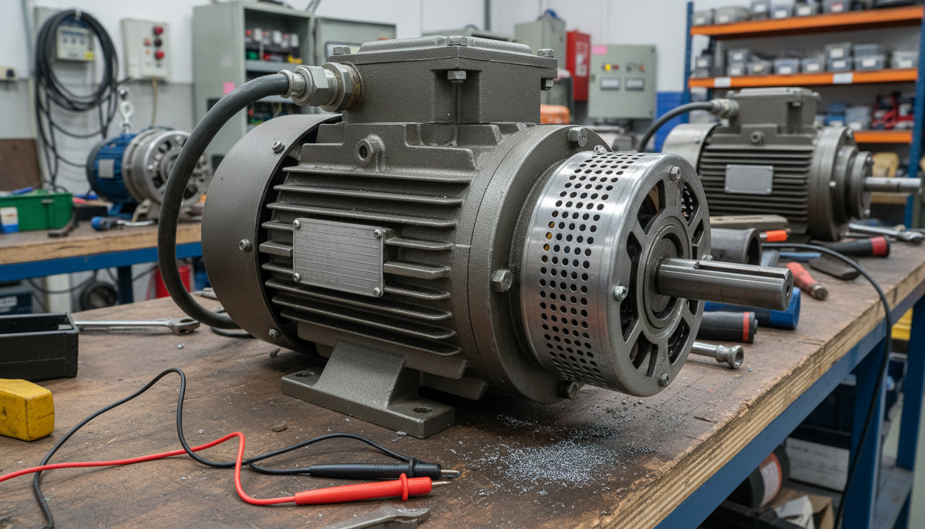
What a Phase-Sequence Tester Can and Cannot Establish
- Can establish: the sequence of the connected three phases relative to the tester’s L1/L2/L3 or equivalent input convention, when used within its rated specifications.
- Cannot alone establish: a complete downstream motor-winding mapping, a drive’s programmed output phase order or actual rotating machinery direction.
- Can support: checking consistency across a designed distribution path, comparing a known-good feeder to an approved replacement and documenting an electrical asset’s supply phase order.
- Cannot substitute for: voltage-absence verification, a complete motor commissioning procedure, manufacturer instructions or physical machine guards.
- Must not be confused with: an ordinary three-phase voltmeter, continuity tester or noncontact voltage detector; those devices do not necessarily provide valid phase-order information.
The Megger three-phase systems application note explains why a reverse sequence can matter for brakes, motors and other direction-sensitive installations. The appropriate test instrument must match the electrical category, frequency and voltage of the actual installation. A qualified worker establishes the site’s method and protective controls.
Electrical Safety Before Any Physical Test
Under OSHA 29 CFR 1910.333, exposed live parts generally must be de-energized before nearby work unless the employer establishes an applicable exception. Only qualified people may work on exposed energized parts under the required protective practices. A phase-order check that needs line voltage is not an informal learner exercise.
A site-specific procedure must address authorized work scope, equipment shutdown and isolation, lockout/tagout, all energy sources and stored energy, a verified absence-of-voltage process where required, appropriate measurement category and voltage limits, rated PPE and arc-flash assessment, and how people remain clear of any possible motor or load movement.
For the training sequence, physical testing is intentionally replaced with interpretation of a hypothetical diagram and supplied manufacturer documentation. Never exchange two energized motor leads, bridge terminal blocks, defeat interlocks, remove a machine guard or spin connected rotating machinery merely to confirm the lesson. Only a qualified technician with an approved plan may perform commissioning operations.
Worked Calculation: Motor Speed Versus Rotation
The synchronous speed of an AC motor’s rotating magnetic field depends on electrical frequency and the number of magnetic poles. For a conventional motor supplied from fixed-frequency three-phase power, the standard relation is:
Ns (rpm) = 120 × f (Hz) ÷ P (poles)
Consider a hypothetical four-pole induction motor operating on a 60 Hz supply. Its synchronous speed is 120 × 60 ÷ 4 = 1,800 rpm. If the actual shaft speed under a particular load is 1,750 rpm, its slip as a percentage of synchronous speed is:
Slip (%) = (Ns − Nr) ÷ Ns × 100
Slip (%) = (1,800 − 1,750) ÷ 1,800 × 100
Slip = 2.78% (rounded)
Reversing the applied phase order reverses the direction of the ideal rotating field, but does not change the 60 Hz electrical frequency or four-pole synchronous-speed magnitude. Actual speed and load characteristics may differ between forward and reverse duty because the driven machine may not be designed to operate equally in both directions. Mechanical rotation must be understood separately from supply RMS voltage balance.
Why Motor Direction Matters to Cooling and Mechanical Equipment
Fans, pumps, compressors, conveyors and material-handling systems frequently specify a required rotation direction. Reversal can reduce flow or pressure, reverse material transport, compromise lubrication or violate a manufacturer’s mechanical requirements. Damage severity depends on equipment design, load and protective systems; never assume that a machine is safe to trial-run backward.
An industrial ventilation fan may retain a spinning shaft while producing less useful flow if the impeller operates in the wrong direction. A pump may likewise rotate while failing to meet its intended hydraulic performance. Motor current and vibration may change, but neither observation is a standalone proof of direction. The direction marked on the machine and the vendor’s commissioning documentation are the reference.

Special Case: Soft Starters, Variable-Frequency Drives, and Bypass
A basic soft starter often changes how motor voltage rises during startup without intentionally changing the incoming phase sequence. However, drive and bypass architectures require model-specific review. Schneider Electric distinguishes the sequence behavior of soft starters and variable-speed drives in its official starter and drive application guidance.
A variable-frequency drive (VFD) synthesizes output switching waveforms; the incoming phase sequence may not determine the output motor rotation in the manner of a direct-on-line supply. The drive’s output terminals and rotation parameters must be evaluated according to the exact model. Schneider’s Altivar troubleshooting guidance warns about differences when a bypass path is present and says direction must be verified separately in drive and bypass operation.
A motor that rotates correctly under a VFD but incorrectly under a bypass may have a mismatch in the separate power paths. A technician must not modify the upstream phase order of an entire distribution board to correct one downstream motor; such a change could reverse other connected loads. Correction, if justified, is a controlled design and commissioning task for qualified staff, not an introductory hands-on lab.
Electrician U, “How Do You Change Rotation Direction in Three Phase Motors” (June 27, 2022). The presentation explains why exchanging phase order reverses motor rotation. Physical wiring demonstrations require appropriate isolation, qualification, equipment controls and site authorization; the lesson’s practical exercise remains documentation-only.
Practical Lab: Verify a Documented Rotation Plan
For a safe training exercise, imagine a new industrial exhaust fan labeled Fan EF-12 with a required rotation direction shown on the OEM drawing. A three-phase source is documented as L1–L2–L3 at a known test location. The technician has not energized the motor; the exercise concerns how to assemble an evidence record before a qualified commissioning team is authorized to work.
- Collect drawings: identify the supply source, motor terminals, disconnect, protective device, drive or starter and any bypass circuit, using approved documents rather than assumed cable colors.
- Identify scope: distinguish the phase-sequence reading at the source from the eventual motor terminal connection and any intervening power electronics.
- Confirm instrument: document the approved phase rotation indicator model, category and voltage/frequency limits from its manual; do not physically connect it during the paper exercise.
- Record the example: treat a hypothetical indicator result of L1–L2–L3 as one documented supply observation. Do not translate it automatically into clockwise shaft rotation.
- Compare requirements: note the intended OEM direction, shaft viewing position, fan guard requirements, and whether a manufacturer-approved nonenergized motor-rotation method exists.
- Plan contingencies: identify who is authorized to perform isolation, testing, possible phase correction and formal re-energization, with hazards and rollback steps.
- Report gaps: if the motor terminal mapping or bypass behavior is unknown, mark the verification incomplete and request the missing drawing or manufacturer’s instructions.
The lab’s success criterion is an accurate, reviewable verification plan, not a spinning motor. A learner should be able to state which evidence is known, which is assumed, and which commissioning actions need a qualified team. Documentation-only practice cannot certify a physical motor’s correct rotation.
Troubleshooting Misleading Indications
- Normal three-phase voltage but wrong mechanical direction: voltage magnitudes do not encode phase order; compare source sequence, terminal mapping and OEM requirements.
- Clockwise indicator disagrees with an expected shaft view: clarify the tester’s lead order and the shaft’s stated viewing direction, then account for VFDs and mechanical reduction gear.
- Unexpected reading or missing indicator: evaluate correct probe identification, instrument limits, missing phase and instrument-specific fault warnings without touching live equipment as an unqualified learner.
- Correct direction in drive mode but not bypass: consider separately wired output paths and documented bypass interlocks.
- Change to one feeder affects several motors: alterations made too far upstream can change phase sequence for multiple downstream loads.
- Apparent motor fault with only a phase-order observation: examine the broader findings from voltage imbalance and current imbalance and single-phasing before reaching a diagnosis.
- Incorrectly assumed standard rotation: consult the actual manufacturer documentation and use an explicitly identified observation point; phase letters alone do not fix every machine’s direction.
Knowledge Check and Answer Guide
- What does a three-phase sequence indicator report? The order of the three connected source phases relative to its test-lead convention, not an independent measurement of motor shaft motion.
- Why can two equally balanced supplies produce opposite motor field directions? Reversing the ordering of two phase connections reverses the stator excitation sequence while retaining balanced voltage magnitudes.
- What is the synchronous speed of a four-pole motor at 60 Hz? 1,800 rpm from 120 × 60 ÷ 4.
- What slip is implied by 1,750 rpm for the hypothetical 1,800-rpm field? Approximately 2.78%; the figure is derived from an assumed speed and does not represent a field measurement.
- Is every counterclockwise indicator reading a dangerous motor installation? No. The displayed rotation is instrument-relative and must be compared with terminal mapping and the intended machine direction.
- Can a basic line sequence meter predict a VFD’s output shaft direction on every model? No. The output sequence and control settings may differ from the incoming line sequence.
- What is the safe learner lab? A documentation-only verification plan that names the expected direction, source, test method, known assumptions and qualified commissioning roles.
- Why should the entire feeder phase order not be changed to correct a single motor? Other downstream equipment may depend on the original phase sequence and could be reversed.
Primary References and Further Reading
Technical and safety references: OSHA 29 CFR 1910.333 — electrical work practices; Megger Application Note 81 — Testing Three Phase Systems; Megger motor and phase rotation instrument information; Fluke 9040 operating manual; and Schneider Electric Altivar phase-rotation troubleshooting. The Fluke Corporation and Electrician U videos are educational complements to the primary equipment and workplace-safety documents.
Elementary Conclusion
Three-phase motor troubleshooting requires more than checking that all line voltages look similar. The intended direction is established by the sequence of stator excitation, the motor’s terminal connection, any drive or bypass power path, and the mechanically driven equipment. A technician must keep supply phase order, rotating-field direction, and actual shaft direction distinct. Correct records and approved safety procedures are prerequisites to any physical correction or commissioning.
Editor’s Note: OSETC.041 advances the independently verified Electrical Technician sequence after OSETC.040. Phase-sequence principles were checked against Fluke, Megger, Schneider Electric and OSHA references on November 6, 2026. Mathematical motor-speed and slip examples are illustrative and were calculated, not physically measured. No energized electrical testing, motor startup or wiring change was performed. The cover and two body illustrations are original AI-generated conceptual editorial images rather than actual equipment test records. Video metadata was checked, while saved WordPress playback and visual release checks are audited separately.

For mobile scanning, display the lesson and original QR image on a laptop or separate screen and scan it with a compatible Bitcoin wallet. Some wallets also support scanning a saved QR image from the same phone. Verify the destination before sending 5,000 sats.
We volunteer daily to ensure the information on this platform is Verifiably True. If you would like to support the research, please scan the QR code.
BitcoinVersus.Tech provides educational information and journalism, not individualized electrical-safety or financial advice.


Leave a Reply