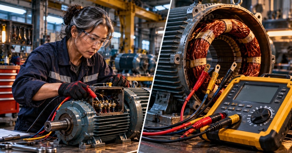
OSETC.038 — Motor Winding Resistance: Measuring Phase Balance Safely. A three-phase motor may trip, overheat, or fail to start because of an open winding, a faulty terminal connection, or a damaged electrical path. An electrical technician can gather one useful clue by comparing low-ohm winding resistance readings across the motor’s phases. This lesson continues OSETC.037 on insulation-resistance testing, but teaches a different measurement: resistance through the copper windings rather than insulation leakage to ground.
Learning Objectives
- Identify winding resistance in ohms (Ω) versus insulation resistance in megohms (MΩ).
- Understand why a six-terminal motor can permit separate coil comparisons, while a three-lead motor may require a different interpretation.
- Follow a safe, documented measurement workflow and recognize when a reading calls for further testing.
Why Motor Winding Resistance Matters
Copper winding conductors and their terminations oppose the flow of current. Each comparable phase of a healthy, similarly constructed three-phase motor should generally have similar resistance when tested in equivalent conditions. A disconnected conductor may show an open circuit. A significantly different value may point to a damaged or corroded connection, a winding defect, incorrect lead identification, or a measurement problem. Fluke’s troubleshooting guidance recommends comparing low-resistance values across three stator phases rather than treating any one measurement as a complete motor-health assessment.
The distinction matters: a motor can have balanced DC winding readings and still have insulation damage, a turn-to-turn defect, or another problem. A balanced result is evidence, not a certificate that a motor is safe to energize.
Safety First: Isolate Before Measuring
This is an observational training lesson, not permission to work inside an energized motor-control center. Motor circuits can retain hazardous energy from variable-frequency drives, capacitors, and mechanical systems. Electrical testing must be performed only by authorized, qualified personnel under site procedures. OSHA’s control-of-hazardous-energy requirements call for proper shutdown, isolation, lockout/tagout, control of stored energy, and verification of deenergization before servicing.
- Identify the motor, its nameplate, and winding terminal diagram before starting.
- Follow the approved energy-control procedure, including lockout/tagout and verification of absence of voltage with an appropriately rated instrument.
- Protect or disconnect attached electronics, drives and other equipment in accordance with the manufacturer and work order.
- Never place a resistance meter across a live circuit. Never use a megohmmeter as a substitute for a low-ohms test.
Video 1 — Six-Terminal Motor Winding Checks
This demonstration focuses on a three-phase motor with identifiable winding ends. The presenter shows how each winding path can be compared with an ordinary digital multimeter after the motor is properly isolated. The six-terminal example is useful for understanding why temporary jumpers or links may need to be accounted for by trained personnel.
Video: The DIY Guy, “How to Test a 3-Phase Electric Motor Like a Pro with a Multimeter!” (August 2026). Open the original tutorial on YouTube if the player is unavailable. Follow your facility’s approved electrical safety practices rather than treating a public demonstration as an operating procedure.
Understanding Three-Lead Versus Six-Lead Readings
A motor with six accessible and correctly identified winding ends may permit separate measurements across matching coils, for example U1–U2, V1–V2, and W1–W2, but only when the connections are appropriate for that motor’s diagram and the work is authorized. This isolates the intended paths for a meaningful comparison.
A motor with three external leads may have its windings joined internally in star (wye) or delta form. Measurements between L1–L2, L2–L3, and L3–L1 then reflect the connected network—not necessarily a single individual coil. Interpreting resistance without understanding that topology can lead to a false conclusion. For underlying three-phase relationships, see OSEEC.008 on three-phase power.
A Safe Measurement and Documentation Workflow
- Prepare the record. Write down the motor identifier, model, connection type, operating history, ambient and winding temperature when available.
- Verify isolation. Only qualified personnel may complete the site’s established LOTO and absence-of-voltage steps and isolate the correct test paths.
- Validate the instrument. Confirm the meter is suitable for the expected low-resistance range; record meter accuracy and check test-lead effects. A dedicated four-wire/Kelvin low-resistance instrument separates current and voltage sensing for greater precision.
- Compare equivalent paths. Measure the intended comparable winding terminals, maintaining clean, stable connections and the same testing conditions.
- Document and escalate. Record each measurement with units and temperature, compare with the OEM specification and historical results, and investigate any unexplained imbalance before service is restored.
Motor-copper resistance changes with temperature. Readings taken just after shutdown should not be compared uncritically with cold factory readings. Also, a general-purpose meter may not resolve very small differences accurately; test-lead resistance and contact quality can obscure low-ohm measurements.
Worked Example — Three Fictional Readings
Suppose a properly isolated training motor has three individually accessible, equivalent coil paths. A technician records 1.20 Ω, 1.21 Ω, and 1.19 Ω at similar temperatures. The mean is 1.20 Ω; the full spread is 0.02 Ω, or approximately 1.67% of the mean. This is a descriptive comparison, not a universal motor acceptance limit. The motor manufacturer’s specifications and the precision of the test setup govern the evaluation.
If instead one equivalent path reads open circuit, the next steps are to verify lead identification, contact quality, jumper placement, and wiring before determining whether the winding is actually open. A value near zero may also arise from test-lead limitations or an unintended parallel path; it does not automatically prove shorted turns.
Video 2 — Comparing Resistance and Continuity
This second demonstration covers continuity, winding resistance comparison, and the distinction between conductor-path checks and body/ground checks with a multimeter. Use it to reinforce the diagnostic questions rather than to copy live-work techniques.
Video: SN TECHNICAL, “3 Phase Motor Testing With Multimeter! How to Check 3 Phase Motor!” (May 2023). Watch directly on YouTube as a fallback. Continuity beeps alone are not precise phase-balance measurements.
How This Differs From the Previous Lesson
OSETC.037 introduced a megohmmeter and a high-resistance insulation path, including safe discharge after testing. This lesson instead focuses on low-resistance copper paths using an appropriately selected ohmmeter. Both tests may contribute to an authorized motor investigation. Fluke’s motor-troubleshooting article describes why multiple checks are needed and why a single passing measurement does not establish motor health.
Knowledge Check
- Why should a technician compare equivalent winding paths rather than just one resistance reading?
- Why are three-lead line-to-line measurements not always readings of single motor coils?
- Does a balanced low-ohm test prove that winding insulation is healthy?
- What safety steps must happen before resistance testing?
Answers: 1. Differences may reveal suspect paths or connection problems. 2. Star/delta internal connections create combined current paths. 3. No; insulation health requires separate appropriate tests. 4. Authorized isolation, lockout/tagout, control of stored energy, and absence-of-voltage verification, following the site’s procedure.
Sources and Conclusion
The central lesson is simple: compare equivalent low-ohm winding paths, account for connection topology and temperature, and never confuse winding resistance with insulation resistance. Further reading: Fluke on sequential motor testing, OSHA on hazardous-energy control, and OSETC.033 on transformer winding fundamentals for adjacent electrical concepts.
BitcoinVersus.Tech Editor’s Note: We volunteer daily to keep technical information useful, educational, and verifiably true. To help sustain independent research and open training, please consider a donation of 5,000 sats using the QR code below.

To scan the QR code, open this lesson on a desktop or larger screen and scan it with your mobile Bitcoin wallet. Thank you for supporting independent technical education.


Leave a Reply