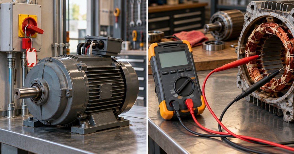
Open-Source Electrical Technician Certification | OSETC.037 | Electrical Testing | Topic: insulation resistance in motors and cables.
Elementary Overview
A conductor is designed to carry electric current; its insulation is designed to keep that current out of other conductors, equipment frames, and people. Insulation resistance testing checks how strongly the insulation opposes a small leakage current. An insulation resistance tester—often called a megohmmeter or “megger”—applies a controlled DC test voltage to isolated, de-energized equipment and reports resistance in megohms (MΩ) or gigohms (GΩ).
This is an electrical testing lesson, not a networking lesson. It follows OSETC.008: Voltage Drop and Loose Connections, OSETC.011: Energy Isolation, and OSETC.016: Motor Starters. Unlike voltage drop under load, an insulation resistance test looks for leakage through or across insulation while the circuit is isolated.
Learning Objectives
- Define insulation resistance and explain what a megohmmeter measures.
- Distinguish an insulation resistance test from a continuity test and a winding-resistance measurement.
- Explain why circuits, electronic drives, and control devices must be isolated and why stored charge must be discharged.
- Recognize phase-to-frame versus phase-to-phase measurements on different motor winding configurations.
- Record, compare, and interpret readings without inventing a universal pass/fail number.
What the Meter Actually Measures
The tester applies a specified DC voltage and measures the tiny resulting current. It calculates resistance using Ohm’s law: R = V ÷ I. For illustration, a hypothetical 500 V test producing 1 µA of measured current corresponds to 500 MΩ. This example explains the math; it does not prescribe a safe test voltage or a passing value for any equipment.
Real readings may change with time because insulation has capacitive charging and dielectric absorption effects. Moisture, contamination, temperature, motor size, cable length, and test duration affect results. A single reading without context is far less useful than a properly documented trend.
Video: Fluke Corporation demonstrates an insulation resistance tester. Viewing the demonstration is not a substitute for site qualification, lockout/tagout, equipment-specific procedures, or manufacturer instructions.
What Is Being Tested?
- Winding-to-frame: checks whether a motor winding’s insulation effectively separates live conductors from the grounded motor frame.
- Conductor-to-ground: checks cable or equipment insulation with the circuit isolated and all connected loads accounted for.
- Phase-to-phase: can be informative only when separate winding groups or conductors are actually isolated; internally connected three-phase windings may naturally show continuity between motor leads.
- Winding resistance: a separate, low-resistance measurement used to compare winding paths; it is not an insulation resistance test.
A three-lead motor may have its winding groups joined internally in star or delta configuration. Applying an insulation resistance test between two leads that are electrically connected through the winding does not isolate insulation between independent windings. Technicians must identify the motor’s winding diagram before interpreting a phase-to-phase result.
Social discussion: practicing electricians compare phase-to-frame and phase-to-phase motor test interpretations. This discussion is a field-perspective illustration, not a governing standard.
Safety and Preparation
Important: insulation testers generate potentially dangerous DC voltages even when the equipment is disconnected from its normal supply. Only qualified personnel following a written site and manufacturer procedure should perform physical testing. The following is a conceptual checklist, not an authorization to test live or unfamiliar equipment.
- Review the equipment nameplate, wiring diagram, instrument manual, and site-approved test plan; determine what is being tested and what must be disconnected.
- Identify every normal and alternate energy source, perform approved isolation/lockout/tagout, and have a qualified person verify absence of voltage with an appropriately rated instrument.
- Isolate the motor windings or cable from connected electronics, including VFDs, PLC cards, sensors, surge protectors, and instruments, as required by their manufacturers; do not apply a megohmmeter across a connected drive.
- Confirm the test method and voltage from the equipment documentation and applicable standard rather than assuming that one setting fits every motor.
- Control the work area and do not touch conductors or leads while a test is active; follow the tester’s manufacturer instructions for connections and operation.
- Allow stored capacitive charge to discharge using the approved method, verify it is safe, restore any disconnected wiring per the procedure, and document all results before returning the equipment to service.
The OSHA electrical work-practice rule, 29 CFR 1910.333, addresses de-energization, lockout/tagout, and verification of the de-energized condition. Fluke’s Insulation Resistance Testing application note explains isolation, temperature effects, and discharge precautions.
How to Read a Test Report
A technician should write down the equipment ID, insulation path, test voltage, duration, reading, temperature, humidity if relevant, test instrument, date, and applicable acceptance criterion. Record whether the test was on new, repaired, or in-service equipment. Correct for temperature or compare like-for-like conditions only according to the applicable procedure.
A high reading alone does not prove a motor is fully healthy; insulation testing may not reveal turn-to-turn shorts or mechanical failures. Likewise, one lower reading does not automatically prove a motor should be condemned: compare the result with the equipment manufacturer’s limits, appropriate standard, previous readings, temperature and moisture conditions. A declining trend can justify further investigation.
Video: motor insulation testing demonstration using an insulation multimeter. All demonstrations are informational; use the instructions and safety controls for the actual equipment in front of you.
Hands-On Learning Without High-Voltage Testing
- Draw a three-phase motor terminal box, the grounded frame, and the isolation boundary.
- Mark which elements must be disconnected before a winding-to-frame insulation test.
- Given a fictional reading of 500 MΩ at 500 V, compute the approximate leakage current using I = V ÷ R (answer: 1 µA).
- Create a blank test report with fields for circuit identification, conditions, measured result and approval.
- Explain why a three-lead motor may show continuity across line terminals even with good insulation to its frame.
Knowledge Check
- What does a megohmmeter measure?
- Why must a VFD and sensitive controls be protected from the applied test voltage?
- Does a single high insulation resistance reading prove the motor has no winding fault?
- What additional information must accompany an MΩ reading?
- Why is phase-to-phase megohmmeter testing not always informative on three-lead motors?
Answers
- Insulation resistance—the opposition to leakage current through or over insulation.
- The higher-than-normal applied DC voltage can damage connected electronics.
- No. It is one diagnostic of insulation condition, not a complete motor health test.
- At minimum, equipment and test points, applied voltage, time, environmental conditions, procedure, and comparison criterion.
- Because windings may be electrically joined internally, the terminals are not necessarily isolated from each other.
Key Takeaways
- Insulation resistance testing is fundamentally about electrical isolation integrity, not networking or software protocols.
- A normal continuity check and a megohmmeter measurement answer different questions.
- De-energize, lock out, verify isolation, protect electronics, and discharge stored energy; use qualified staff.
- Interpret trends against equipment-specific criteria rather than an invented universal MΩ threshold.
References and Further Reading
- OSHA — 29 CFR 1910.333 Electrical Work Practices.
- Fluke — Insulation Resistance Testing (application note).
- Fluke official video — How to Measure Insulation Resistance.
BitcoinVersus.Tech Editor’s Note: We volunteer daily to ensure the credibility of the information on this platform is Verifiably True. If you would like to support to help further secure the integrity of our research initiatives, please donate using the QR code provided

For best QR-code scanning results, please scan this donation code from a desktop or larger screen. Mobile screens may prevent camera recognition.


Leave a Reply