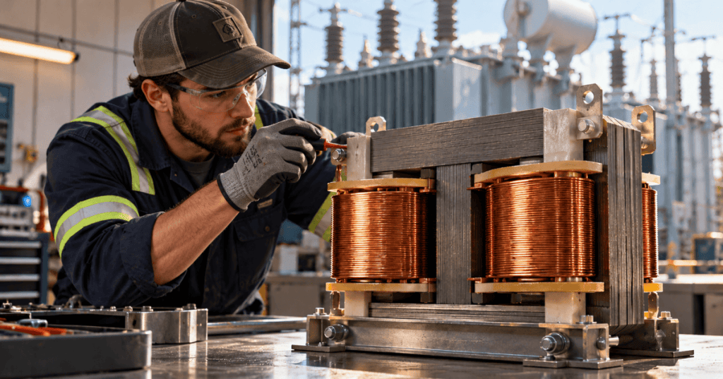
Open-Source Electrical Technician Certification | OSETC.033 | Electrical Power | Transformer Fundamentals.
Elementary Overview
An electrical transformer transfers alternating-current energy between circuits through a changing magnetic field. It can increase voltage (step up), decrease voltage (step down), or provide electrical isolation, depending on its design and connections. Transformers are essential in electrical distribution, industrial facilities, and data centers because equipment rarely operates at the same voltage used by the upstream power system.
This lesson fills a foundational electrical gap. Start with OSETC.005 on Ohm’s law and OSETC.001 on power and apparent power if voltage, current, and kVA are unfamiliar.
Learning Objectives
- Identify the primary winding, secondary winding, and magnetic core of a two-winding transformer.
- Explain why an alternating magnetic field induces secondary voltage.
- Calculate an ideal turns ratio and interpret what happens to current.
- Read common transformer nameplate information, especially volts, kVA, frequency, and impedance.
- Describe safety boundaries for inspection without attempting energized transformer work.
How a Transformer Works
In a conventional two-winding transformer, AC applied to the primary winding creates changing magnetic flux in a shared core. That changing flux induces a voltage in the secondary winding. The two coils are not normally connected to each other electrically: energy moves through magnetic coupling. This is why a correctly designed isolating transformer can separate circuits galvanically while still transferring power.
The core is usually made from thin laminated magnetic steel or another suitable magnetic material; lamination helps limit eddy-current losses. Copper or aluminum windings carry current. The insulation system separates windings from each other and the core. Heat, vibration, moisture, and loading all matter to transformer service life.
Step-Up and Step-Down Transformers
A step-down transformer has fewer secondary turns than primary turns and reduces voltage. A step-up transformer has more secondary turns and raises voltage. For the idealized AC relationship, Vp / Vs = Np / Ns, where V represents voltage and N represents winding turns.
Example: a transformer with 400 primary turns and 200 secondary turns has a 2:1 turns ratio. With an ideal 480 V AC input, its secondary voltage is 240 V AC. It is a voltage conversion, not free extra electrical power.
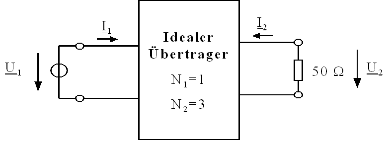
In the ideal approximation, the current ratio goes in the opposite direction: Ip / Is = Ns / Np. A step-down transformer can support a larger secondary current at lower voltage for approximately the same apparent power; actual current depends on the connected load, rated capacity, and losses. Do not use turns-ratio math to select field wiring or overcurrent protection.
kVA and Nameplate Ratings
Electrical technicians often encounter transformer nameplates marked in kilovolt-amperes (kVA), not just kilowatts (kW). kVA is apparent power, combining the voltage and current capacity without assuming a particular load power factor. A transformer marked 15 kVA is not automatically a 15 kW source under every load condition.
Consider a hypothetical, single-phase nameplate: 15 kVA, 480 V primary, 240 V secondary, 60 Hz. For the rated ideal apparent-power calculation, primary full-load current would be 15,000 VA ÷ 480 V = 31.25 A; secondary full-load current would be 15,000 VA ÷ 240 V = 62.5 A. These figures illustrate the relationship, not a field-installation specification. Three-phase current calculations use a different formula.
- Primary and secondary voltage: the winding ratings and allowed connection arrangement.
- kVA: the transformer’s rated apparent-power capacity under specified conditions.
- Frequency (Hz): the design operating frequency; a conventional transformer changes voltage, not frequency.
- Impedance (%Z): a characteristic affecting voltage regulation and available short-circuit current; it is not the same as a winding-resistance reading.
- Cooling, temperature rise, and insulation class: information about heat removal and material limits.
- Tap information: manufacturer-provided voltage adjustment options; tap changes are not a casual adjustment and require appropriate qualified procedures.
What Technicians Look For During an Approved Inspection
Before any inspection involving exposure to conductors, the technician must follow the applicable site procedures and qualification requirements. OSETC.011 explains lockout/tagout and energy isolation. A transformer can have more than one possible source, and backfeed, stored energy, induced voltage, and adjacent energized equipment create hazards even when one disconnect is open. Do not remove covers, change taps, probe terminals, or open winding connections without authorization and a verified safe work condition.
For a suitably authorized visual inspection, the work order and manufacturer’s instructions may direct attention to identification, warning labels, unusual odors, evidence of overheating, blocked cooling openings, leakage on liquid-filled equipment, corrosion, damaged insulation, abnormal noise, and environmental conditions. Observations are documented and escalated; they do not justify touching exposed parts.
Grounding and bonding require particular care. A transformer secondary may be a separately derived system depending on the installation. The appropriate grounding-electrode, system-bonding, and equipment-bonding arrangements must be determined from the actual configuration and applicable code, not guessed from a transformer’s voltage ratio. Review OSETC.012: Grounding and Bonding for the introductory concepts.
Social discussion: practicing electricians discuss transformer grounding. The discussion is a field-perspective illustration, not a governing code or permission to work energized.
The linked electrician discussion illustrates the types of practical questions that arise around step-up transformers and bonding. It is an authentic field discussion, not an authoritative wiring diagram or approval to work on energized equipment. For electrical-work practices, refer to OSHA and the applicable installation standards.
Transformer Testing Is a Separate Procedure
A basic turns-ratio explanation is not permission to energize a transformer for testing. Commissioning tests, polarity checks, winding resistance, insulation resistance, and dissolved-gas analysis (where applicable) answer different questions and use different qualified procedures. OSETC.037 covers insulation-resistance testing fundamentals, including the need to protect electronics and safely discharge stored energy.
Knowledge Check
- Question 1: What connects two separate transformer windings magnetically? Answer: changing magnetic flux in the common magnetic path.
- Question 2: If an ideal 480 V primary has twice as many turns as the secondary, what is the secondary voltage? Answer: 240 V.
- Question 3: Why does the nameplate use kVA? Answer: because transformer capacity is rated in apparent power, rather than assuming a fixed load power factor.
- Question 4: Does disconnecting the primary alone prove that every transformer terminal is safe to touch? Answer: no; backfeed and other hazards must be considered through verified isolation procedures.
Key Takeaways
- Primary and secondary windings transfer AC energy through changing magnetic flux.
- The turns ratio determines the ideal voltage ratio; current changes inversely for equal apparent power.
- kVA, rated voltage, frequency, impedance, and thermal information all matter on a nameplate.
- Transformer inspection and testing require equipment-specific instructions, verified electrical safety, and qualified personnel.
References and Further Reading
- U.S. Energy Information Administration — Batteries, Circuits, and Transformers.
- OSHA — 29 CFR 1910.333, Electrical Work Practices.
- OSHA — 29 CFR 1910.305, Transformer Installation Requirements.
- Wikimedia Commons — Transformer Voltage and Current Example (Public Domain).
BitcoinVersus.Tech Editor’s Note: We volunteer daily to ensure the credibility of the information on this platform is Verifiably True. If you would like to support to help further secure the integrity of our research initiatives, please donate using the QR code provided

For best QR-code scanning results, please scan this donation code from a desktop or larger screen. Mobile screens may prevent camera recognition.


Leave a Reply