
Modbus RTU is one of the most common ways industrial devices exchange small amounts of control and measurement data over serial wiring. A PLC, drive, meter, remote I/O module, or instrument can share one RS-485 bus as long as the devices agree on the electrical wiring, serial settings, device addresses, and Modbus message format.
This lesson follows OSETC.031: HART Communication, OSETC.030: Process Transmitter Calibration, and OSETC.027: 4–20 mA Current Loops. HART adds digital information to an analog current loop; Modbus RTU instead moves structured digital messages over a serial data link.
What You Should Learn
- What Modbus RTU is and what RS-485 contributes.
- How a two-wire multidrop RS-485 bus is normally arranged.
- Why baud rate, parity, data bits, and stop bits must match.
- How device addresses, function codes, coils, and registers work.
- What a Modbus RTU frame contains and why CRC matters.
- How to recognize common wiring, configuration, addressing, and timing faults.
- How to perform a basic technician-level Modbus RTU checkout.
Start With The Two Layers
It helps to separate RS-485 from Modbus RTU. RS-485 describes the electrical serial interface: differential signaling over a balanced pair, multidrop wiring, and physical-layer behavior. Modbus RTU defines the messages carried over that link: device address, function code, data, timing, and CRC error checking. A device can use RS-485 without Modbus, and Modbus can also run over transports other than RS-485.
Wire RS-485 As A Bus
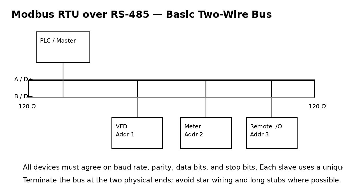
A typical two-wire RS-485 installation uses one differential pair running from device to device. The physical ends of the bus are terminated to match the cable impedance; 120 Ω is common in industrial RS-485 practice. Long star branches and excessive stubs can create reflections and unreliable communication, especially as cable length and baud rate increase.
Terminal labels are a field trap. Vendors may use A/B, D+/D−, +/−, or other conventions, and the A/B naming convention is not perfectly consistent across every product family. If communication fails after a new device is added, verify the manufacturer’s terminal definitions rather than assuming the letters mean the same thing on both devices.
Match The Serial Settings
Every device on a Modbus RTU segment must use compatible serial framing. The important settings are baud rate, parity, data bits, and stop bits. A common field configuration is written in a compact form such as 19200 8E1: 19,200 bit/s, 8 data bits, even parity, and 1 stop bit.
Example serial configuration
Baud rate: 19200
Data bits: 8
Parity: Even
Stop bits: 1
Mode: Modbus RTU
If one device is set to 9600 baud and the rest are at 19200, the wiring can be perfect and communication will still fail. The same is true for parity mismatch. Always record the working serial settings before changing them.
Give Every Server A Unique Address
On a traditional Modbus serial line, one client/master initiates requests and addressed server/slave devices respond. The Modbus serial-line guide allows normal slave addresses from 1 through 247; address 0 is reserved for broadcast behavior. Two devices with the same address can produce collisions, confusing responses, or apparent intermittent faults.
A basic commissioning sheet should record the physical device, its RS-485 address, baud/parity settings, and the register map being used.
Device        Address    Serial settings
VFD-1         1          19200 8E1
Power meter   2          19200 8E1
Remote I/O    3          19200 8E1
Understand Function Codes And Data Types
Modbus messages use function codes to say what operation is requested. The official Modbus application protocol defines common functions such as 01 Read Coils, 02 Read Discrete Inputs, 03 Read Holding Registers, 04 Read Input Registers, 05 Write Single Coil, 06 Write Single Register, 15 Write Multiple Coils, and 16 Write Multiple Registers.
| Function | Typical Meaning | Data Type |
|---|---|---|
| 01 | Read coils | 1-bit outputs/status |
| 02 | Read discrete inputs | 1-bit inputs |
| 03 | Read holding registers | 16-bit registers |
| 04 | Read input registers | 16-bit registers |
| 05 | Write single coil | 1 bit |
| 06 | Write single register | 16 bits |
| 15 | Write multiple coils | Multiple bits |
| 16 | Write multiple registers | Multiple 16-bit registers |
Do not guess a register map. A drive may place output frequency in one holding register while a power meter uses completely different addresses and scaling. Use the exact manufacturer register table for the device and firmware version being commissioned.
Read A Basic RTU Frame
A Modbus RTU request contains the target device address, a function code, function-specific data, and a two-byte CRC error-check value. For example, a request to read holding registers might conceptually contain:
[Address] [Function] [Start Address] [Quantity] [CRC]
   01        03          0000          0002     ....
The receiver recalculates the CRC from the received bytes. If the calculated value does not match the transmitted CRC, the frame is considered corrupted. CRC failures often point technicians toward electrical noise, wiring faults, incorrect serial interpretation, or damaged frames—not toward an incorrect engineering value in a register.
Remember The Addressing Offset Trap
Modbus documentation can show human-readable register numbers such as 40001, while the protocol request itself may use a zero-based address such as 0. The official protocol specification defines PDU addresses starting at zero for many functions. Software packages and vendor manuals do not all display addresses the same way, so an apparent “off-by-one” problem is extremely common.
If the device responds but the value is wrong or the software reports an illegal data address, check whether the tool expects zero-based offsets, five-digit reference numbers, or the raw address from the vendor register map.
Troubleshoot In A Fixed Order
- Power: verify every field device is powered and healthy.
- Physical pair: confirm the RS-485 conductors and reference/shield arrangement match the device manuals.
- Topology: verify bus wiring, termination at the two physical ends, and reasonable stub lengths.
- Serial settings: confirm baud rate, parity, data bits, and stop bits.
- Address: confirm the target device address is unique and matches the poll.
- Function: confirm the device supports the requested function code.
- Register: confirm the register address, offset convention, data type, byte/word order, and scaling.
- Traffic: look for requests leaving the master and responses returning from the correct slave.
- CRC/errors: investigate noise, polarity, grounding, shielding, cable, and timing when corrupted frames appear.
Use A Known-Good Poll First
Before attempting writes, prove that you can read one known register from one device. A good first test is a read-only value that is easy to verify locally, such as measured line voltage, device status, frequency, temperature, or firmware identification. Once one known read succeeds, expand the poll gradually.
A technician should avoid random writes to live drives, breakers, outputs, or process equipment. Writing the wrong coil or register can start, stop, reset, or reconfigure real equipment. Use the vendor map, follow the site’s change-control and safety procedures, and test write operations only when the consequence is understood.
Practical Exercise
A power meter is configured for address 2, 19200 baud, 8 data bits, even parity, and 1 stop bit. The vendor manual says measured voltage is available using Function 03 at raw register offset 100 and returns one 16-bit value scaled by 0.1 V.
- Set the polling tool to
19200 8E1. - Select Modbus RTU and slave/server address
2. - Select Function 03 Read Holding Registers.
- Enter starting offset
100and quantity1. - If the raw response is
4032, apply the scale factor:4032 × 0.1 = 403.2 V. - If no response arrives, return to wiring, serial settings, address, and bus termination before changing register scaling.
Knowledge Check + Answers
- Is RS-485 the same thing as Modbus RTU? No. RS-485 is the physical serial interface; Modbus RTU is a protocol carried over it.
- What settings must match across the link? Baud rate, data bits, parity, stop bits, and RTU mode.
- Why must device addresses be unique? The master/client needs one unambiguous responder for each addressed request.
- What does Function 03 do? Read holding registers.
- What is the purpose of CRC? Detect corruption in the received RTU frame.
- Where is termination normally installed? At the two physical ends of the RS-485 bus.
- What is a common register-addressing mistake? Confusing displayed register numbers with zero-based protocol offsets.
- What is the safest first communication test? Read one known, read-only register whose value can be independently verified.
Primary References
- Modbus Organization — Specifications and Implementation Guides
- Modbus Application Protocol Specification V1.1b3
- Modbus Serial Line Protocol and Implementation Guide V1.02
Elementary Review
Modbus RTU troubleshooting becomes easier when you separate the layers. First prove the RS-485 bus is wired correctly. Then prove the serial settings match. Then prove the address and function code are correct. Finally verify the register map, offset convention, data format, and scaling. Moving through those layers in order is much faster than changing random settings.
Editor’s Note
The featured image is an original 1200×630 BitcoinVersus.Tech lesson cover created specifically for OSETC.032 and is not reused in the body. The body uses a separate original 1200×675 RS-485 bus diagram. The lesson contains three unique, directly relevant English-language YouTube videos implemented as responsive native Gutenberg 16:9 embed blocks, plus one directly relevant English-language Reddit social embed. Ordinary lesson prose is not placed inside bordered, shaded, card, callout, panel, or fixed-width text boxes.
BitcoinVersus.Tech content is provided for informational and educational purposes.


Leave a Reply