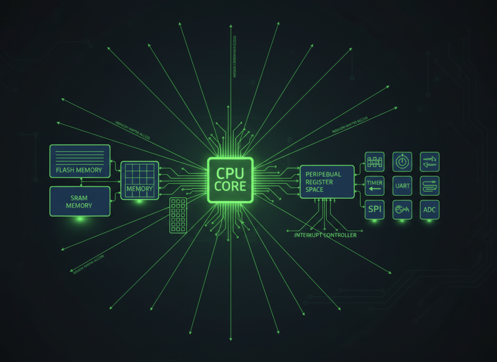
Firmware engineering begins where software meets silicon: the processor executes instructions, memory maps define what addresses mean, registers expose hardware state, and interrupts let external events redirect execution.
This is OSFEC.001, the first lesson in the Open Source Firmware Engineer Certification track. It builds on OSFTC.001: Firmware Images, Safe Flashing, Bootloaders, and Recovery Basics and moves from technician-level service into engineering-level architecture: CPU core, memory regions, peripheral registers, vector tables, interrupts, priorities, timing, and faults.
The system model
CPU executes instructions → memory system resolves addresses → flash/SRAM/peripheral regions respond → hardware changes state → events generate interrupts → interrupt controller prioritizes service → handler executes → normal execution resumes
1. A microcontroller is more than a CPU
A modern microcontroller commonly integrates a processor core with flash, SRAM, timers, GPIO, serial interfaces, ADC/DAC blocks, clocks, watchdogs, DMA, interrupt logic, and debug hardware on one device.
The Armv8-M architecture lesson provides useful background. At the firmware-engineer level, the key question becomes how software sees and controls those hardware blocks.
2. The memory map is the firmware engineer’s floor plan
A memory map assigns address regions to different resources such as executable code, SRAM, peripheral registers, and system-control blocks.
Arm’s Cortex-M documentation describes common architectural regions for code, SRAM, peripheral space, and the private peripheral/system-control area. The exact usable addresses depend on the specific microcontroller and must come from the chip vendor’s reference manual and datasheet.
Reference: Arm Cortex-M memory model.
Video 1: Cortex-M fundamentals, memory maps, registers, and interrupts
3. Memory-mapped I/O connects software to peripherals
In a memory-mapped I/O design, peripheral control/status registers occupy addresses in the processor’s address space. Firmware uses ordinary processor memory-access mechanisms to interact with them.
The important engineering insight is that a peripheral register is not ordinary RAM. Reading or writing it can acknowledge an event, start a conversion, change a pin, update a timer, or alter another hardware function.
4. Register semantics matter
Hardware registers can be read/write, read-only, write-only, write-one-to-clear, write-one-to-set, self-clearing, latched, or reserved. The same software access pattern is not safe for every register type.
That is why firmware engineers must treat the reference manual as part of the codebase: register meaning, reset state, valid field values, side effects, and timing requirements are all part of software correctness.
5. Why volatile appears around hardware
Hardware state can change independently of ordinary program flow. In C and C++, hardware-facing register definitions are therefore commonly declared with volatile-style qualifiers so the compiler preserves the required accesses.
But volatile is not a synchronization primitive. It does not automatically make shared data atomic, race-free, thread-safe, or interrupt-safe.
6. Bitfields are where features live
A single hardware register often contains multiple independent fields. One field may select operating mode, another may enable an event, another may report status, and some bits may be reserved.
Firmware engineers therefore think in fields, masks, and state transitions rather than treating every register as one undifferentiated number.
7. Processor state matters during interrupts
The Program Status Registers in Armv8-M Architecture lesson explains the status-register side of CPU state.
When an exception or interrupt occurs, the processor must preserve enough state to execute a handler and then return to the interrupted code correctly. Cortex-M processors automate important parts of this exception entry and return process.
8. Polling versus interrupts
Polling means software repeatedly checks hardware state. Interrupts allow hardware events to request CPU service asynchronously.
Polling can be simple and deterministic for small systems. Interrupts become important when multiple asynchronous events need bounded response without constant CPU attention. The correct architecture depends on timing, power, complexity, and reliability requirements.
9. The vector table connects events to handlers
The vector table stores handler addresses for reset, processor exceptions, and device-specific interrupts. CMSIS documents the common Cortex-M vector-table model and the processor exceptions shared across Cortex-M variants.
Reference: CMSIS-Core Interrupts and Exceptions / NVIC.
Video 2: Cortex-M interrupts and the NVIC
10. What the NVIC manages
Arm Cortex-M systems use the Nested Vectored Interrupt Controller (NVIC) to manage external interrupts and configurable exception priorities.
- Enable state: whether a source is allowed to interrupt.
- Pending state: whether an event is waiting for service.
- Active state: whether a handler is currently executing.
- Priority: which event should run first or preempt another.
CMSIS provides standardized APIs and data structures around these architectural functions so firmware does not need to reinvent the processor-core interface for every device.
11. Priority numbering is easy to misunderstand
On Cortex-M NVIC designs, lower numerical priority values represent higher urgency. The number of priority bits implemented is device-specific, so the effective number of usable priority levels can vary across microcontrollers.
12. Keep interrupt handlers bounded
A well-designed interrupt handler usually does the minimum work necessary to preserve the event and keep the system responsive. Long handlers increase latency for lower-priority work and make timing failures harder to reproduce.
Common design patterns include capturing the time-sensitive state in the handler and deferring larger processing to the main loop or an RTOS task.
13. Shared state creates race conditions
If normal program code and an interrupt handler can access the same variable or hardware resource, the ordering of those accesses matters. A read-modify-write sequence can be interrupted halfway through and produce lost updates or inconsistent state.
Solutions can include atomic operations, tightly bounded critical sections, message passing, queues, or other synchronization mechanisms chosen for the architecture and latency requirement.
14. Interrupt latency is an engineering budget
Interrupt response is not instantaneous. A realistic latency path includes the event itself, pending state, any higher-priority work, processor exception entry, and the time required for the handler to reach the critical service point.
Firmware engineers therefore analyze worst-case response, not only average behavior.
For systems that later use an RTOS, this timing model expands into task scheduling and context switching. Arm’s current Cortex-M context-switching learning path is a useful bridge into that topic.
15. Faults are part of the exception system
Firmware debugging is not only about peripheral interrupts. Cortex-M architectures also use exceptions for fault conditions such as invalid memory access, bus faults, usage faults, and hard faults, depending on the specific core.
A production fault strategy should preserve enough diagnostic evidence to determine what failed, where execution was interrupted, which fault status was active, and whether the system can recover safely.
Video 3: Cortex-M exceptions, priorities, and faults
16. Timing and ordering can be subtler than source-code order
Real processors and buses can include pipelines, buffers, and peripheral timing rules. That means engineers sometimes need architecture-defined synchronization or memory-ordering mechanisms so hardware observes operations in the required sequence.
Arm documents these cases in Application Note 321: Cortex-M memory barrier instructions. Such mechanisms belong only where the architecture or device documentation requires them.
17. Good firmware architecture preserves hardware visibility
Production firmware often separates responsibilities into layers:
- device/register definitions;
- peripheral drivers;
- hardware abstraction;
- application/state-machine logic.
Too little abstraction spreads silicon-specific assumptions everywhere. Too much abstraction can hide the timing and hardware behavior engineers need to understand. Good architecture makes the boundary explicit.
18. Engineer’s diagnostic sequence
- Confirm the exact MCU and reference manual.
- Confirm clocks and reset state.
- Confirm which memory/peripheral region is involved.
- Inspect relevant control and status information.
- Confirm pin multiplexing and peripheral ownership.
- Confirm interrupt source, vector mapping, enable state, and priority.
- Inspect fault/status information if execution failed.
- Measure timing with appropriate lab tools where needed.
- Reduce the issue to the smallest reproducible hardware/software interaction.
- Only then rebuild the higher-level abstraction.
Practice exercise
A timer is counting correctly, but the expected interrupt-driven action never occurs.
- Which architectural layers must be checked?
- How can a peripheral-event problem be distinguished from an interrupt-routing problem?
- Why can correct timer operation coexist with a missing handler call?
- What happens if the event remains pending or is never acknowledged?
- How can priority configuration affect response?
- If execution faults instead, what diagnostic information should be preserved?
Knowledge check
1. What is a memory map?
A definition of which address regions correspond to code, data memory, peripherals, and system resources.
2. What is memory-mapped I/O?
A design where hardware registers occupy processor address space and are accessed through normal memory operations.
3. Does volatile make shared interrupt data race-free?
No. It preserves observable access semantics but does not provide atomicity or synchronization.
4. What does the vector table do?
It associates reset, exception, and interrupt events with their handler entry addresses.
5. What does the NVIC manage?
Interrupt enable, pending/active state, prioritization, and exception delivery on Cortex-M.
6. Why keep handlers bounded?
To control interrupt latency and protect responsiveness of other work.
7. Why does the exact MCU reference manual matter?
Because the architecture defines the framework, but the silicon vendor defines actual peripherals, addresses, register semantics, options, and errata.
Key takeaway
Firmware engineering is hardware-aware software engineering. Correct design depends on accurate memory-map knowledge, register semantics, interrupt and fault behavior, timing constraints, and shared-state discipline.
Engineering note: Architectural descriptions in this lesson are educational. Implementation must follow the exact processor architecture manual, silicon-vendor reference manual, datasheet, startup code, CMSIS/device headers, and errata for the target MCU.
BitcoinVersus.Tech
Advertisement
Editor’s Note:
We volunteer daily to ensure the credibility of the information on this platform is Verifiably True. If you would like to support our research initiatives, please donate here: 3C9o19EH5HSiwEPyCTmEKzxhNCbo2X6TTb
BitcoinVersus.tech is not a financial advisor. This media platform reports on financial subjects purely for informational purposes.


Leave a Reply