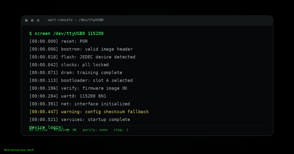
A serial console is often the fastest path to understanding why embedded hardware will not boot, configure, or recover normally. Correct use requires identifying the electrical interface, establishing the correct UART parameters, capturing the entire startup sequence, and separating transport problems from real firmware faults.
OSFTC.002 continues the Open Source Firmware Technician Certification track from OSFTC.001: Firmware Images, Safe Flashing, Bootloaders, and Recovery Basics. The earlier lesson introduced UART, SWD/JTAG, bootloaders, image verification, and recovery. This lesson develops UART into a disciplined diagnostic tool.
The engineer-level companion track begins with OSFEC.001: Microcontroller Architecture — Memory Maps, Registers, and Interrupts. Firmware technicians do not need to redesign the UART peripheral, but they must understand enough of the transport to recognize electrical, framing, and software-level failures.
Serial-console diagnostic flow
identify target → identify ground/TX/RX and logic voltage → confirm adapter compatibility → connect ground → cross TX/RX correctly → select baud/data/parity/stop settings → open terminal → reset target → capture from first character → classify output quality → identify boot stage → preserve logs → compare with known-good boot → escalate or recover using the approved method
UART as a firmware service interface
UART stands for Universal Asynchronous Receiver/Transmitter. It sends serial data without a shared clock line. The transmitter and receiver must therefore agree closely enough on timing and frame format to sample each bit correctly.
A basic service console often uses three electrical connections:
- TX: data transmitted by one device;
- RX: data received by one device;
- GND: common electrical reference.
TX and RX are normally crossed between devices: target TX connects to adapter RX, and target RX connects to adapter TX.
MIT: point-to-point serial communication principles
Logic-level UART is not RS-232
One of the most important technician checks is electrical level compatibility. A microcontroller header labeled UART commonly uses TTL/CMOS logic levels such as 1.8 V, 3.3 V, or 5 V. Traditional RS-232 uses very different signaling voltages and polarity conventions.
Connecting a true RS-232 interface directly to a low-voltage MCU UART can damage the target. Before connection, verify:
- target UART voltage;
- USB-to-UART adapter logic voltage;
- whether the adapter automatically level-shifts;
- pinout and header orientation;
- whether the target is self-powered;
- whether adapter VCC should remain disconnected.
Cornell University’s ECE4760 UART reference uses the same practical rule for USB-to-UART service work: connect ground, cross TX/RX, and avoid applying an adapter supply to a target unless the circuit explicitly requires it. See Cornell ECE4760 UART Serial.
Baud rate and bit time
The baud rate determines the nominal number of serial symbols transmitted per second. For common UART configurations with one bit per symbol, baud rate is effectively the serial bit rate.
bit time = 1 / baud rate
At 115200 baud, one bit lasts approximately 8.68 microseconds. A common 8N1 frame contains one start bit, eight data bits, no parity bit, and one stop bit, for ten bit-times per byte.
Approximate payload throughput for continuous 8N1 traffic is therefore:
bytes per second ≈ baud / 10
University of Texas at Austin: UART background
Frame format
A UART frame commonly contains:
- idle state;
- start bit;
- data bits, commonly seven or eight;
- optional parity;
- one or more stop bits.
The common notation 115200 8N1 means 115200 baud, eight data bits, no parity, and one stop bit.
If the terminal is configured for the wrong baud or frame parameters, output may appear as random symbols, repeated blocks, partial readable text, or nothing at all.
University of Texas at Austin: UART operation
Common service baud rates
Typical values encountered in embedded systems include:
- 9600;
- 19200;
- 38400;
- 57600;
- 115200;
- 230400;
- 460800;
- 921600.
These are common values, not a license to guess indefinitely. Prefer schematics, vendor service documentation, firmware source, known-good logs, or measurement with an oscilloscope/logic analyzer.
Recognizing a baud-rate mismatch
A wrong baud rate often produces repeatable garbage rather than truly random output. The same reset can generate the same pattern of incorrect characters each time because the receiver is consistently sampling at the wrong intervals.
- No output: wrong pin, wrong ground, wrong port, target not transmitting, wrong voltage, or missing boot activity.
- Consistent garbage: baud mismatch or frame mismatch is likely.
- Readable text with occasional corruption: marginal timing, poor ground, noise, level mismatch, cable quality, or target instability may be involved.
- Readable early boot then garbage: firmware may reconfigure the UART clock or baud later in boot.
The University of Texas serial-communication material notes that excessive baud mismatch can create framing errors because the receiver samples the stop bit at the wrong time. See UT Austin — Serial Communication and UART.
Pin identification
Unlabeled service headers require caution. Common methods for identifying pins include:
- schematic or boardview documentation;
- PCB silkscreen;
- continuity to known ground;
- measuring idle voltage with a multimeter;
- observing candidate TX pins during reset with an oscilloscope or logic analyzer;
- tracing to the MCU datasheet pinout.
A UART TX line commonly idles high at the target’s logic voltage and becomes active during boot. This is a clue, not universal proof; other digital lines can behave similarly.
Connect receive-only first when uncertainty is high
When the purpose is only to observe boot output, a conservative technique is to connect target TX to adapter RX plus ground and leave adapter TX disconnected initially. This reduces the chance of accidentally sending characters, break conditions, or bootloader commands to an unknown device.
Bidirectional operation can be added after the pinout, voltage, and terminal settings are confirmed.
Capture from reset, not after failure
The most valuable boot messages often occur in the first second after reset. Opening the terminal after the device has already failed can miss:
- reset cause;
- ROM bootloader version;
- DRAM initialization;
- flash detection;
- partition selection;
- signature verification;
- watchdog reset history;
- fallback-slot selection;
- filesystem mount errors;
- kernel panic or RTOS fault;
- early configuration migration.
Open the capture tool first, then reset or power-cycle the target using the approved procedure.
Boot stages technicians should recognize
A typical embedded boot sequence may contain several layers:
- ROM / immutable boot code: first-stage silicon initialization;
- primary bootloader: selects and validates the next image;
- secondary bootloader: may initialize memory, storage, networking, or recovery services;
- kernel or RTOS: establishes scheduling and device drivers;
- root filesystem / application services: starts product-specific functions;
- workload: final intended device behavior.
The diagnostic objective is to identify the last stage that is known to be functioning.
Reading reset causes
Many devices report why the processor reset. Common causes include:
- power-on reset;
- external reset pin;
- watchdog timeout;
- brownout;
- software-requested reset;
- fault or exception;
- security or boot-validation failure.
A repeating watchdog reset with the same timestamp pattern strongly suggests the application reaches a point where it stops servicing the watchdog or encounters a recurring deadlock/fault.
Interpreting common boot-log failures
- flash device not found: storage power, bus, chip-select, part compatibility, or physical failure;
- bad magic / invalid header: wrong image, corrupted partition, wrong address, or incomplete update;
- signature verification failed: image integrity/authenticity problem, wrong key, rollback restriction, or corrupted bytes;
- mount failed: filesystem corruption, missing partition, incompatible layout, or storage fault;
- kernel panic / hard fault: software fault, invalid memory access, driver issue, corrupted image, or hardware instability;
- network init timeout: PHY, driver, clock, link, EEPROM/configuration, or interface problem;
- configuration checksum failure: corrupted or incompatible persistent data, possibly followed by defaults or fallback.
Capture tools
Common terminal tools include:
- PuTTY;
- Tera Term;
- screen;
- minicom;
- picocom;
- CoolTerm;
- vendor IDE serial monitors.
The specific program is less important than correct settings and reliable logging. A useful capture preserves timestamps where possible, terminal settings, the exact reset action, and the complete output.
Linux serial-console examples
A Linux host might expose a USB serial adapter as /dev/ttyUSB0 or /dev/ttyACM0. Example commands include:
screen /dev/ttyUSB0 115200
picocom -b 115200 /dev/ttyUSB0
minicom -D /dev/ttyUSB0 -b 115200
Permissions vary by distribution. Technician workflows should use the site’s approved access method rather than changing device permissions casually.
Windows serial-console workflow
On Windows, verify the COM port in Device Manager, then configure the terminal for the documented baud and framing settings. If several USB serial adapters are attached, unplug/replug identification or adapter serial numbers can prevent capture from the wrong port.
Interactive bootloaders
Some bootloaders provide a countdown during which a keypress opens an interactive console. This can expose commands for:
- listing partitions;
- displaying environment variables;
- selecting boot slots;
- loading recovery images;
- examining memory or flash;
- changing boot targets;
- starting network recovery.
Do not modify boot variables merely because a prompt is available. Record the original values and follow the approved recovery procedure.
Break signals and unintended input
Some bootloaders interpret a UART break condition or specific characters as a recovery request. A terminal program, faulty adapter, or incorrect connection can therefore change boot behavior.
If boot behavior changes only when the console adapter is connected, investigate whether the adapter is driving TX, applying unintended power, holding reset-related circuitry, or generating a break condition.
Logic analyzer confirmation
When terminal output remains unreadable, a logic analyzer can measure bit timing and decode candidate UART settings. This is especially useful when documentation is missing.
- measure idle voltage;
- estimate bit width;
- calculate approximate baud;
- test data-bit, parity, and stop-bit assumptions;
- compare decoded bytes with expected ASCII or boot patterns.
At 115200 baud, a measured bit width near 8.7 microseconds is a strong clue that 115200 is correct.
When the serial console is silent
A silent console can still contain useful diagnostic information.
- Verify target power and current behavior.
- Confirm common ground.
- Confirm the expected TX pin is active at reset.
- Check whether output is on a different UART instance.
- Check whether firmware disables console output in production mode.
- Check whether secure boot suppresses or restricts console access.
- Check whether the processor leaves reset.
- Escalate to SWD/JTAG or vendor recovery only after the non-invasive checks are complete.
Known-good log comparison
A known-good boot log is one of the strongest service references. Compare failing and healthy devices by stage rather than only by final error line.
- first missing line;
- first changed version or identifier;
- timing differences;
- repeated retries;
- different reset cause;
- different partition or boot slot;
- new hardware-detection failure;
- configuration migration differences.
Serial-console field checklist
- Identify the exact hardware revision.
- Find the documented UART service header when available.
- Verify logic voltage before attaching an adapter.
- Confirm common ground.
- Cross target TX to adapter RX and target RX to adapter TX.
- Begin receive-only if the target is uncertain.
- Set the documented baud and frame parameters.
- Open logging before reset.
- Capture the entire boot sequence.
- Record reset cause and firmware/bootloader identifiers.
- Identify the last successful boot stage.
- Compare against known-good output.
- Preserve the raw log before editing or summarizing it.
- Use interactive recovery commands only under an approved procedure.
- Document the final state and evidence.
Exercises
- A console configured at 115200 baud produces stable but unreadable characters. List the first checks that should be performed.
- Calculate the approximate bit time at 9600 baud and at 115200 baud.
- Explain why adapter TX may initially be left disconnected during an unknown-board investigation.
- Describe the difference between logic-level UART and traditional RS-232.
- A board emits readable bootloader text and then becomes silent immediately after “starting application.” Identify several plausible fault classes.
- A logic analyzer measures a bit period close to 104 microseconds. Estimate the likely baud rate.
- Build a boot-stage comparison table for one healthy and one failing device.
- Create a ticket note containing terminal settings, adapter identity, target revision, reset cause, and the first failing boot-log line.
Knowledge check
Why are TX and RX normally crossed?
The transmitting output of one device must feed the receiving input of the other.
What does 115200 8N1 mean?
115200 baud, eight data bits, no parity, and one stop bit.
What is the first electrical quantity to verify before connecting a USB-to-UART adapter?
The target UART logic voltage and adapter compatibility.
What does repeatable garbage text usually suggest?
A baud-rate or frame-format mismatch is a common cause.
Why should logging begin before reset?
Critical boot-ROM and bootloader diagnostics may appear only during the earliest startup stage.
Why is a known-good boot log valuable?
It reveals the first stage where the failing unit diverges from normal behavior.
When should SWD/JTAG become the next step?
After the approved non-invasive serial and power checks are complete and low-level recovery or debug access is required.
What is the diagnostic objective when reading a long boot log?
Identify the last known-good stage and the first meaningful divergence or failure.
Key takeaway
A serial console converts an opaque boot failure into a sequence of observable stages. Reliable diagnosis depends on correct electrical levels, correct UART timing, complete capture from reset, disciplined log comparison, and preservation of the recovery path. The most useful technician question is not merely “what error appears?” but “what is the last subsystem that definitely initialized correctly?”
Safety and service note: Serial headers can expose raw processor I/O pins. Verify voltage, ground, pinout, adapter behavior, and site authorization before connection. Do not apply adapter power or send bootloader commands unless the approved procedure requires it.
Display note: this lesson uses standard Gutenberg paragraphs, headings, lists, preformatted terminal examples, and media embeds only. No decorative text-box or callout-box layout is used.
BitcoinVersus.Tech
Advertisement
Editor’s Note:
We volunteer daily to ensure the credibility of the information on this platform is Verifiably True. If you would like to support our research initiatives, please donate here: 3C9o19EH5HSiwEPyCTmEKzxhNCbo2X6TTb
BitcoinVersus.tech is not a financial advisor. This media platform reports on financial subjects purely for informational purposes.


Leave a comment