
Elementary Overview
I²C is a two-wire serial bus used to connect microcontrollers to sensors, EEPROMs, displays, power-management devices, and many other peripherals. Its two signals are serial data, SDA, and serial clock, SCL. The protocol is simple enough to learn quickly, but reliable products require more than calling a library function. Firmware engineers must understand addressing, open-drain electrical behavior, pull-up resistance, ACK/NACK handling, clock stretching, timeouts, bus recovery, and what real waveforms look like on an oscilloscope or logic analyzer.
This lesson follows OSFEC.006: Direct Memory Access and complements the diagnostic habits used in OSFTC.007: SPI NOR Flash Diagnostics. It also builds on the older BitcoinVersus.Tech primer Serial Communication and Its Role in Data Transmission. The goal is to move from “the sensor library works” to “I can explain and diagnose the bus electrically and in firmware.”
What You Should Learn
- Why SDA and SCL use open-drain signaling and require pull-up resistors.
- How 7-bit addressing, read/write direction, ACK, and NACK fit into a transaction.
- How bus capacitance and rise-time limits constrain pull-up resistor values.
- What clock stretching, arbitration, and repeated START mean to firmware.
- How to recognize common faults such as a wrong address, missing pull-ups, a stuck-low line, or excessive rise time.
- How to build timeouts and bus-recovery behavior into firmware rather than assuming the bus always succeeds.
1. Why Two Wires Can Support Many Devices
An I²C controller starts communication and generates the clock. Target devices listen for their address and respond when selected. Most everyday devices use a 7-bit address. One bus can therefore connect many peripherals as long as their addresses do not conflict and the electrical loading remains within specification.
A typical transaction begins with a START condition, followed by the target address and a direction bit. The receiver answers with ACK if it accepts the byte or NACK if it does not. Data bytes follow, each with its own ACK/NACK phase. The controller eventually sends STOP, unless it needs a repeated START to change direction without releasing the bus.
Address scanners are useful during bring-up because they ask each legal address whether a device acknowledges. They are not proof that a driver is correct. A scanner can find a device while your production transaction still fails because the register address, byte order, timing, voltage, or transaction sequence is wrong.
2. Open-Drain Signaling Changes How You Think About Logic HIGH
I²C devices normally pull SDA and SCL LOW but do not actively drive them HIGH. When every device releases a line, an external pull-up resistor brings it back toward the supply voltage. This wired behavior allows multiple devices to share the bus without two outputs directly fighting each other.
The practical consequence is that a logic HIGH is not instantaneous. The pull-up resistor and total bus capacitance create an RC rise. Long traces, cables, connectors, level translators, more devices, and oscilloscope probes can all add capacitance. A bus that looks perfect at 100 kHz may fail when increased to 400 kHz because the signal no longer rises quickly enough.
3. Engineering the Pull-Up Resistors
Pull-up design is a range, not a magic value. The resistor must be large enough that a device can pull the line LOW without exceeding its sink-current limit, but small enough that the line rises within the timing requirement for the selected I²C mode.
A useful lower-bound equation is RP(min) = (VCC − VOL(max)) / IOL. A useful upper-bound approximation from the I²C rise-time relationship is RP(max) = tr / (0.8473 × Cb). For an example 3.3 V bus with VOL(max) = 0.4 V and IOL = 3 mA, the minimum is about 967 Ω. If Fast-mode allows a 300 ns rise time and the bus capacitance is 100 pF, the maximum is about 3.54 kΩ. A standard value such as 2.2 kΩ falls inside that example range.
Those numbers are an example, not a universal recommendation. Real engineering uses the exact device limits, bus capacitance, operating mode, temperature range, voltage, and power budget. If the design barely meets the equation on paper, inspect the actual waveform rather than trusting the nominal resistor alone.
Related social discussion: I²C pull-up selection and field reliability on LinkedIn.
4. Clock Stretching, Arbitration, and Repeated START
A target may hold SCL LOW to delay the controller while it prepares data. This is clock stretching. A robust driver must know whether the MCU peripheral supports it, what timeout policy applies, and what should happen if the line never releases.
I²C can also support multiple controllers. Arbitration works because a controller watches the actual bus while transmitting. If it releases SDA expecting HIGH but observes LOW, another controller has asserted LOW and won that bit. Even single-controller products benefit from understanding arbitration because the same open-drain electrical behavior explains why the bus can detect contention without destructive output fighting.
A repeated START lets a controller begin another transfer without issuing STOP. Register reads frequently use this pattern: write a register index, issue repeated START, switch to read, and then receive the requested bytes. Treating every read as a separate STOP/START sequence can break devices whose datasheets require a combined transaction.
5. A Firmware Driver Needs Explicit Failure States
Production firmware should distinguish at least these outcomes: success, address NACK, data NACK, timeout, arbitration loss, bus error, and bus-busy or stuck-line conditions. Collapsing all failures into a generic “I²C error” makes field diagnosis much harder because software loses the evidence needed to tell an absent device from a damaged bus.
For a simple probe routine, the logic is conceptually: attempt the address, wait only for a bounded interval, record ACK or the specific error, and continue. For a production sensor driver, add bounded retries, timestamps, error counters, and a recovery policy. Do not build an infinite retry loop around a shared hardware bus.
A good driver also separates transport from device protocol. The I²C layer should know how to transmit and receive bytes reliably. A higher device layer should know that register 0x0F is an identity register, or that two bytes represent temperature. This separation makes it easier to test bus behavior independently from sensor interpretation.
6. Bus Lockup and Recovery
A common field failure occurs when SDA remains LOW after a reset, brownout, interrupted transaction, or target malfunction. Reinitializing the MCU peripheral alone may not help because the external device is still waiting for clock edges or a reset condition.
The NXP I²C specification defines bus-clear behavior. If SDA is stuck LOW, a controller can provide clock pulses so a target has a chance to finish its internal state and release SDA. If SCL itself is held LOW, the preferred recovery may require a device reset or power cycle. Firmware engineers should implement this only within the electrical and timing constraints of their hardware; some MCUs require temporarily switching I²C pins to GPIO for recovery.
7. Debug the Waveform, Not Just the API Return Code
A logic analyzer answers digital questions: Was START present? Which address was transmitted? Did the target ACK? Was there a repeated START? Which byte NACKed? An oscilloscope answers electrical questions: Did the HIGH level reach a valid voltage? How long was the rise time? Is there ringing, noise, or a slow edge? Does SCL remain LOW during clock stretching?
Use both views when possible. A logic decoder can display clean-looking bytes even when the analog margin is poor. Conversely, a beautiful square-looking waveform does not prove the software is talking to the correct address or register.
8. Common Failure Patterns
- No ACK at any address: verify power, ground, SDA/SCL pin mapping, pull-ups, voltage levels, and whether the target is held in reset.
- Device appears at the wrong address: check address-select pins and whether the datasheet quotes a 7-bit address or an 8-bit address byte.
- Works at 100 kHz but fails at 400 kHz: inspect rise time, total capacitance, pull-up value, and level translators.
- Random NACKs in the field: check supply integrity, EMI, connector quality, temperature, pull-up margin, and timeout handling.
- SDA stuck LOW after reset: investigate interrupted transfers, target state, bus-clear recovery, hardware reset, and power sequencing.
- Only one of two identical sensors works: check address conflicts; fixed-address devices may require configurable address pins, a multiplexer, or separate buses.
- Reads return shifted or nonsensical data: verify repeated START requirements, register width, byte order, signedness, and whether the correct register pointer was written first.
Practical Exercise
- Choose one I²C sensor datasheet and record its supply voltage, 7-bit address, maximum bus speed, register-address width, and repeated-START requirements.
- Draw a controller, two targets, SDA, SCL, and two pull-up resistors. Explain why no device should normally drive either line HIGH.
- For a hypothetical 3.3 V bus, calculate a pull-up range using the device sink-current limit and the bus rise-time/capacitance limit.
- Write pseudocode for a bounded I²C address scanner that records ACK, NACK, and timeout separately.
- Describe what you would expect to see on a logic analyzer when a target NACKs its address.
- Write a recovery decision tree for SDA stuck LOW, SCL stuck LOW, and repeated transient NACKs.
Knowledge Check + Answers
- Why are pull-ups required? Because I²C devices normally pull the shared lines LOW and release them for HIGH; the resistor creates the HIGH state.
- Why can a resistor be too large? The RC rise becomes too slow to meet the bus timing requirement.
- Why can a resistor be too small? Devices may have to sink excessive current to create a valid LOW.
- What does an ACK prove? A receiver accepted the preceding byte at the bus level; it does not prove the higher-level data is semantically correct.
- What is clock stretching? A target holds SCL LOW to delay the controller.
- Why is repeated START useful? It lets the controller continue a combined transaction, often switching from writing a register index to reading data without releasing the bus.
- What is the first tool for a mystery NACK? Start with the datasheet and a logic analyzer; use an oscilloscope when electrical margin is in question.
- What should firmware avoid? Infinite retries, unbounded waits, and error handling that discards the specific cause.
Primary References
- NXP — UM10204 I²C-bus specification and user manual
- Texas Instruments — I²C Bus Pullup Resistor Calculation
Elementary Conclusion
I²C becomes much easier to engineer once you stop treating it as only a software library. SDA and SCL are shared electrical signals with real RC behavior. Addresses, ACK/NACK, repeated START, clock stretching, timeouts, pull-up sizing, and recovery all interact. A firmware engineer who can read the transaction and the waveform can solve problems that remain invisible when debugging only from application code.
Editor’s Note
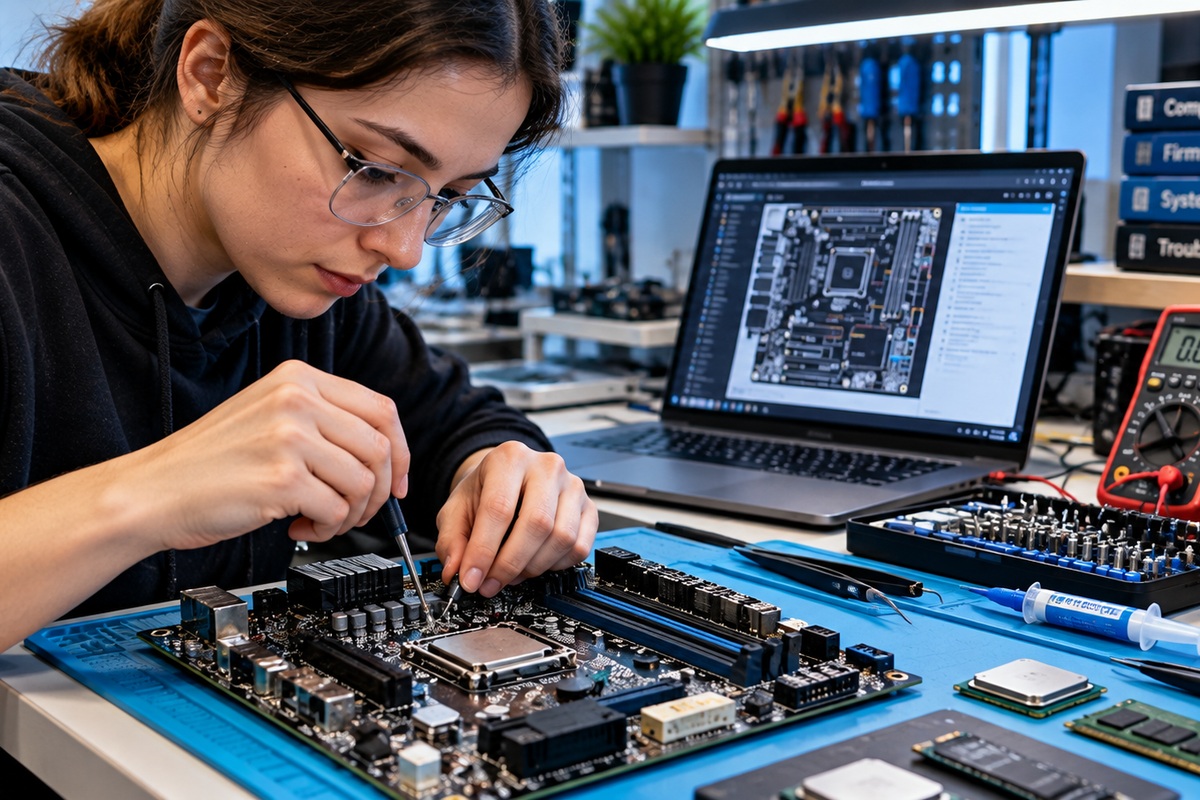
This lesson uses original artwork created specifically for OSFEC.007. The featured image is not reused in the body. The equations and numerical example are educational; production designs should use the exact limits from the applicable I²C mode, MCU datasheet, peripheral datasheets, and measured bus capacitance.
We volunteer daily to ensure the credibility of the information on this platform is Verifiably True. If you would like to support our research initiatives, please donate here: 3C9o19EH5HSiwEPyCTmEKzxhNCbo2X6TTb
BitcoinVersus.Tech content is provided for informational and educational purposes.


Leave a Reply