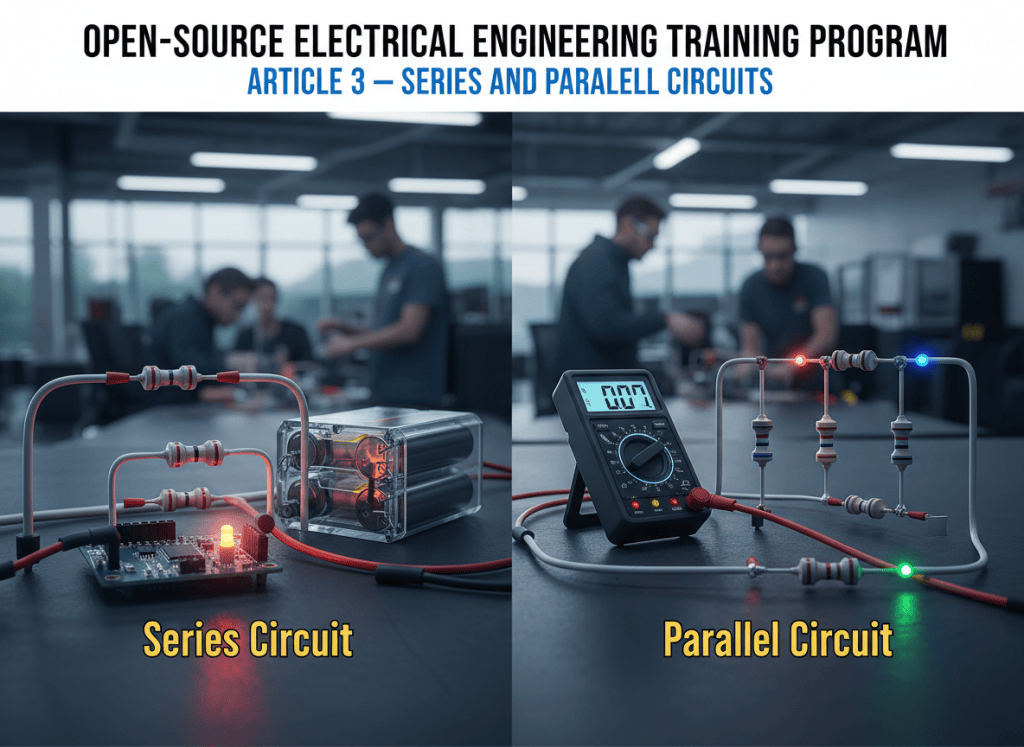
The BitcoinVersus.Tech Open-Source Electrical Engineering Training Program continues with Article 3. This lesson builds on voltage, current, resistance, and power by showing how components behave when they are connected in series or in parallel.
In simple terms: Series and parallel describe how you connect parts in a circuit. Imagine two lamps powered by a battery. In series, electricity has one route through both lamps, one after the other. Disconnect either lamp and you break that route, so both go out. In parallel, each lamp has its own route across the battery. Disconnect one lamp and the other can stay on. Remember: series means one path; parallel means separate paths.
Definitions: A circuit is an electrical path; current needs a complete return path to flow. A series connection puts components along one path. A parallel connection puts components on separate branches connected across the same two points. A load uses electrical energy, such as a lamp or motor. A node is a connection point shared by circuit parts.
Series Circuits
In a series circuit, components share one current path. The same current flows through each component. The source voltage is divided among the loads, and the individual voltage drops add to the source voltage.
For resistors in series:
R_total = R1 + R2 + R3 + ...Example: three resistors of 10 Ω, 20 Ω, and 30 Ω in series have a total resistance of 60 Ω. With a 12 V source, Ohm’s law gives I = V/R = 12/60 = 0.2 A. That same 0.2 A flows through every resistor.
Parallel Circuits
In a parallel circuit, components are connected across the same two electrical nodes. Each branch therefore has the same voltage across it, while total current is the sum of the branch currents.
For resistors in parallel:
1/R_total = 1/R1 + 1/R2 + 1/R3 + ...For two parallel resistors, the shortcut is R_total = (R1 × R2) / (R1 + R2). Two 20 Ω resistors in parallel therefore produce 10 Ω total resistance.
What a Technician Should Remember
- Series: current is the same through every component.
- Series: voltage drops add to the source voltage.
- Series: resistances add directly.
- Parallel: voltage is the same across every branch.
- Parallel: branch currents add to total current.
- Parallel: equivalent resistance is lower than the smallest individual branch resistance.
Field Application
These relationships appear constantly in electrical and data-center work. Loads are commonly arranged in parallel so each receives the intended supply voltage and can operate independently. Series relationships appear inside equipment, control circuits, sensing networks, battery strings, and voltage-divider circuits. Being able to identify the topology from a schematic is a basic troubleshooting skill.
Measurement Practice
With equipment de-energized and made safe according to the applicable procedure, identify which components share a single path and which connect across common nodes. For energized measurements, use properly rated instruments, PPE, and approved procedures. A voltmeter is connected across the points whose potential difference is being measured, while an ammeter measures current in the current path. Never move meter leads between current and voltage configurations without verifying the meter setup first.
Worked Check
A 24 V source supplies two 12 Ω resistors in parallel. Their equivalent resistance is 6 Ω. Total source current is therefore 24/6 = 4 A. Because the resistors are equal, each branch carries 2 A. Each resistor still has the full 24 V across it.
Video Reference
The Organic Chemistry Tutor provides a detailed worked tutorial covering the same series and parallel circuit concepts and calculations used in this lesson.
Continue Learning
Practice identifying series and parallel sections before doing calculations. Once that becomes automatic, mixed circuits can be reduced section by section. The next training articles will continue toward circuit laws, measurement, safety, grounding and bonding, AC/DC systems, power distribution, transformers, three-phase systems, switchgear, schematics, troubleshooting, and data-center electrical systems.
References: Khan Academy electrical engineering material on series and parallel circuits; Vernier series and parallel circuit experiment resources; The Organic Chemistry Tutor video reference.
Related BitcoinVersus.tech coverage: Electrical voltage/current/power · Line-to-line vs line-to-neutral · Enphase 800 VDC · ABB 800 VDC
BitcoinVersus.Tech Editor’s Note: We volunteer daily to help ensure the credibility of information on this platform is verifiably true. BitcoinVersus.tech is not a financial advisor. This article is independent reporting and educational content for informational purposes only.


Leave a Reply