Elementary Overview
A microcontroller does not automatically know where a compiled program belongs in memory. The linker script tells the build system which parts of the program belong in Flash and which parts need RAM; the startup code then prepares those memory regions before main() begins. The vector table tells an Arm Cortex-M processor where the initial stack and interrupt handlers are located, while the stack and heap reserve RAM for temporary function state and dynamic allocation. This lesson connects the architecture from OSFEC.001, the task memory demands of OSFEC.002, and the GDB/OpenOCD debugging workflow from OSFEC.003.
The Linker Script Turns a Memory Map Into an Executable Layout
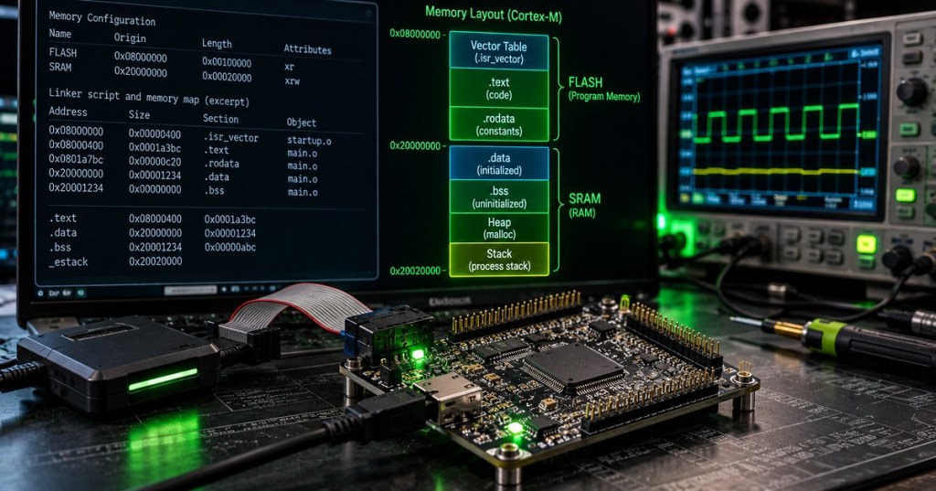
A compiler produces object files containing code and data, but the linker decides their final addresses. A GNU linker script commonly defines memory regions such as FLASH and RAM, then maps output sections into those regions. On a Cortex-M device with Flash beginning at 0x08000000 and SRAM beginning at 0x20000000, the linker script can place the vector table and program code in nonvolatile Flash while reserving writable data for SRAM. This is the software expression of the hardware memory map; if the addresses, sizes, alignment, or region permissions are wrong, a perfectly valid C or C++ program can still fail before normal application logic runs.
.text, .rodata, .data, and .bss Have Different Jobs
The .text section normally contains executable instructions, while .rodata stores read-only constants; both can usually remain in Flash. .data contains writable variables that have nonzero initial values, so their initial bytes are stored in the firmware image but copied into RAM during startup. .bss contains zero-initialized or uninitialized static-storage objects and usually consumes RAM without requiring equivalent initialized bytes in the Flash image. The linker also emits symbols that startup code can use to locate the beginning and end of these regions. Reading the generated map file makes these relationships visible and helps explain why a binary can run out of SRAM even when plenty of Flash remains.
Startup Code Builds the C Runtime Before main()
After reset, low-level startup code creates the environment expected by compiled C or C++. A typical Reset_Handler copies the initial values for .data from their load address in Flash to their run address in RAM, fills .bss with zeros, performs any processor or clock initialization required by the platform, may call C/C++ runtime constructors, and finally branches to main(). If the copy boundaries are wrong, initialized global variables contain bad values; if .bss is not cleared, code that assumes zero initialization starts with unpredictable state. These failures often appear in early boot logs or under a hardware debugger before the application reaches its normal scheduler.
The Vector Table Connects Reset and Interrupts to Code
On a typical Arm Cortex-M reset sequence, the processor obtains the initial Main Stack Pointer (MSP) from the first vector-table entry and the reset vector from the next entry, then begins fetching instructions from the reset handler. Additional table entries identify exception and interrupt handlers. The vector table therefore has both a linker-placement requirement and a runtime meaning: the image must place it where the processor or vector-table offset configuration expects it. A bootloader may relocate or replace this table when handing control to an application image, which is why vector-base errors can make a firmware image appear to flash successfully but fault immediately after reset.
Stack and Heap Turn Remaining RAM Into Runtime Capacity
The stack stores call frames, return state, local variables, saved registers, and interrupt or exception context. The heap supplies dynamic allocations such as malloc() when the firmware chooses to use them. In an RTOS, each task may also receive its own stack, making stack sizing a system-level memory-budget problem rather than one global number. Stack overflow, heap fragmentation, allocation failure, or stack/heap collision can corrupt unrelated data and create failures that look random. Engineers therefore inspect linker boundaries, RTOS stack high-water marks, static-analysis estimates, fault addresses, and worst-case call depth instead of assuming unused-looking RAM is safe capacity.
Load Address and Run Address Can Be Different
Advanced linker layouts distinguish where bytes are stored from where they execute. Code can be stored in Flash but copied to RAM for faster execution; initialized data can be stored in Flash yet run from SRAM; bootloaders and application images can occupy separate Flash banks; and special sections can be aligned for DMA, caches, nonvolatile settings, or memory-protection boundaries. GNU linker scripts express these choices with region placement and load addresses, while startup code performs any required copying. This same concept matters during the firmware flashing process because a programmer writes the stored image, not an abstract view of where every section will eventually execute.
Verify the Built Image Before Blaming the Hardware
A firmware engineer should inspect the build artifacts before treating a boot failure as an electrical problem. The ELF file, linker map, section sizes, symbols, disassembly, and debugger memory reads can prove where the toolchain actually placed code and data. Useful GNU Arm commands include arm-none-eabi-size firmware.elf, arm-none-eabi-objdump -h firmware.elf, and arm-none-eabi-nm -n firmware.elf; the exact tool names depend on the installed toolchain. Then OpenOCD and GDB can halt the target, inspect the program counter and stack pointer, compare the vector table against the ELF, and verify whether execution reached the reset handler or main(). This evidence-first workflow complements the checksums, golden images, and rollback discipline in OSFTC.003.
Minimal GNU Linker-Script Example
MEMORY
{
  FLASH (rx)  : ORIGIN = 0x08000000, LENGTH = 512K
  RAM   (rwx) : ORIGIN = 0x20000000, LENGTH = 128K
}

SECTIONS
{
  .isr_vector : { KEEP(*(.isr_vector)) } > FLASH
  .text       : { *(.text*) *(.rodata*) } > FLASH
  .data       : { *(.data*) } > RAM AT> FLASH
  .bss        : { *(.bss*) *(COMMON) } > RAM
}
Worked Example
- Flash: 512 KiB beginning at 0x08000000.
- SRAM: 128 KiB beginning at 0x20000000.
- .text + .rodata: 92 KiB stored and executed from Flash.
- .data: 6 KiB of initialized variables stored in the Flash image and copied to SRAM at reset.
- .bss: 18 KiB of SRAM zeroed during startup.
- RTOS task stacks: six tasks × 2 KiB = 12 KiB reserved.
- Remaining SRAM before heap, buffers, interrupt stack, and margin: approximately 92 KiB.
- Engineering conclusion: Flash utilization alone cannot establish memory safety; RAM must be budgeted across sections, stacks, buffers, heap, DMA needs, and reserve margin.
Engineering Checklist
- Confirm the MCU Flash and RAM origins and lengths from the device memory map.
- Confirm the vector table is placed at the address expected after reset or bootloader handoff.
- Verify .text, .rodata, .data, and .bss placement in the linker map.
- Verify startup code copies initialized data and clears .bss before application use.
- Check linker symbols used by Reset_Handler against the generated map file.
- Budget stack, RTOS task stacks, heap, DMA buffers, and persistent buffers explicitly.
- Check alignment requirements for vectors, DMA, caches, and special memory regions.
- Inspect the ELF with size, objdump, nm, or equivalent toolchain utilities.
- Compare debugger PC/SP and vector-table contents against the exact ELF build.
- Archive the map file and build identity with the firmware release.
Exercises
- Explain why .data needs both a load address and a run address on a typical MCU.
- Explain why .bss consumes RAM but usually does not need equivalent initialized bytes in the firmware image.
- Draw the reset sequence from vector-table fetch through Reset_Handler to main().
- Given 64 KiB SRAM, calculate remaining capacity after 8 KiB .data, 20 KiB .bss, and four 4 KiB task stacks.
- Describe what could happen if the initial stack pointer in the vector table points outside valid SRAM.
- Use a sample map file and identify the largest five symbols consuming SRAM.
- Explain when executing selected code from RAM can be useful.
- Describe how GDB can distinguish “never reached Reset_Handler” from “failed after entering main().”
Knowledge Check + Answers
- What does a linker script control? It assigns compiled sections and symbols to addresses and memory regions in the final executable image.
- Where does .text usually live? In nonvolatile program memory such as Flash.
- Why is .data copied at startup? Its initial values are stored in the firmware image, but writable variables must run from RAM.
- Why is .bss cleared? C and C++ require zero initialization for objects with static storage duration that do not have explicit nonzero initializers.
- What are the first two Cortex-M vector entries normally used for? The initial main stack pointer and reset-handler address.
- What does a map file provide? A human-readable view of linked sections, addresses, sizes, symbols, and object-file contributions.
- Why can an RTOS increase RAM pressure? Multiple tasks commonly require separate stacks plus kernel objects and communication buffers.
- Why keep the exact ELF and map file for a release? They let engineers translate addresses, crashes, and debugger state back to the exact firmware layout that shipped.
Elementary Conclusion
A firmware program is like a set of supplies that must be placed in the correct rooms before work can begin. The linker script decides which pieces belong in Flash and which belong in RAM. The vector table tells the processor where its first stack and first instruction are. Startup code moves initialized information into RAM, clears the area that must begin at zero, and then starts the normal program. The stack holds temporary work for functions and interrupts, while the heap can supply memory that is requested while the system is running. When engineers read the map file and compare it with the real microcontroller memory map, they can explain where every important byte went instead of guessing. That is what turns a compiled firmware file into a predictable system that can boot, run, and be debugged reliably.
BitcoinVersus.Tech
Advertisement
Editor’s Note:
We volunteer daily to ensure the credibility of the information on this platform is Verifiably True. If you would like to support our research initiatives, please donate here: 3C9o19EH5HSiwEPyCTmEKzxhNCbo2X6TTb
BitcoinVersus.tech is not a financial advisor. This media platform reports on financial subjects purely for informational purposes.


Leave a comment