Elementary Overview
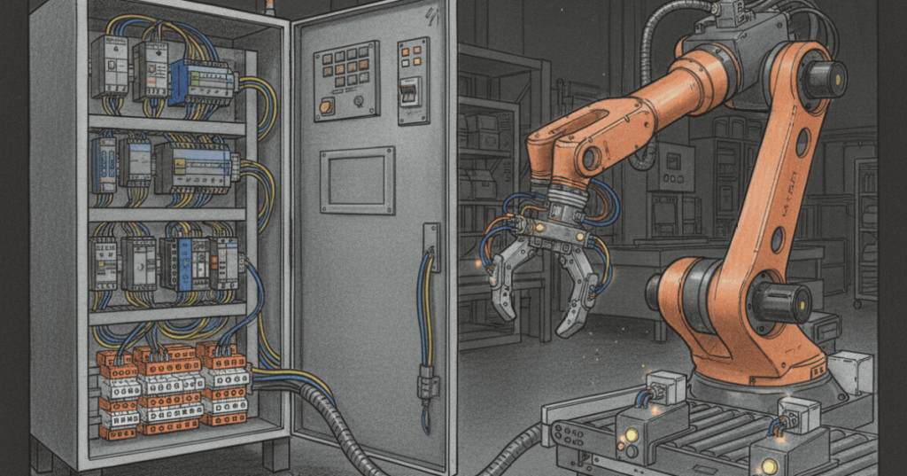
An industrial robot does not work alone. It must exchange signals with a PLC, sensors, conveyors, end effectors, and safety devices so the entire workcell knows when it is safe and ready to move. The simplest signals are digital inputs and digital outputs: an input tells the robot what is happening outside the controller, while an output tells another device what the robot wants or what state it is in. A good technician learns to follow the entire handshake: command → output → field device → sensor feedback → input → next robot or PLC action.
Digital Inputs And Outputs Are The Basic Robot Interface
A robot digital input (DI) may receive a part-present signal, gripper-closed confirmation, conveyor-ready state, or permissive from the PLC. A digital output (DO) may command a solenoid valve, turn on a stack light, tell the PLC that the robot is busy, or request another machine to start. When troubleshooting, never assume the software name matches the physical wire: confirm the I/O address, terminal, voltage state, and controller monitor screen. The same principle applies to limit switches and proximity sensors and photoelectric sensors: verify the field device and the controller state separately.
A Handshake Prevents Two Machines From Guessing
A handshake is a defined sequence of signals that lets the robot and PLC confirm each step before continuing. A common pattern is PLC_READY → ROBOT_READY → CYCLE_START → ROBOT_BUSY → CYCLE_COMPLETE. Fault and reset signals are usually separate. The exact signal names vary by manufacturer, but the logic is the same: neither controller should rely on an unexplained time delay when a positive status signal can prove that the previous step actually happened. This is the same control philosophy used by interlocks and permissives.
End Effectors Need Command And Feedback Signals
A robot gripper should not be treated as “close and hope.” A technician may command DO_GRIP_CLOSE = ON, then wait for DI_GRIP_CLOSED = ON or DI_PART_PRESENT = ON before allowing the robot to retract. If the output changes but the input never follows, split the fault into stages: controller output, wiring, valve or electric actuator, mechanical grip, and feedback sensor. That prevents unnecessary reteaching of robot positions when the real problem is electrical or pneumatic.
Safety Signals Are Not Ordinary Production I/O
Robot safety uses dedicated safety-rated circuits and functions for emergency stops, guard doors, enabling devices, safe speed, and other protective states. A normal PLC bit that says “door closed” is not automatically equivalent to a safety-rated guard interlock. Technicians must know which signals are standard production I/O and which are safety I/O, follow the approved workcell safety design, and never bypass a protective device just to make the cycle run. If a gate opens, the safety system should force the robot into the defined safe condition before ordinary production logic can resume.
Troubleshoot The Signal Path In One Direction At A Time
When a robot will not start, trace the signal path instead of changing several things at once. Begin at the device that should create the signal, check power and wiring, confirm the PLC or robot input changes, verify the logic condition, then follow the resulting output to the next device. Use the teach pendant I/O monitor where supported, and compare it with the PLC I/O table or controller diagnostics. If the robot moves correctly in manual mode but refuses automatic operation, look for missing ready, remote, cycle-start, safety, or fault-reset conditions before suspecting mastering or calibration.
Worked Example: Basic Robot–PLC Cycle Handshake
- 1. PLC sets
PLC_READY = 1after conveyor and fixture checks pass. - 2. Robot confirms no fault and sets
ROBOT_READY = 1. - 3. PLC sends a one-cycle or edge-detected
CYCLE_START. - 4. Robot clears
ROBOT_READY, setsROBOT_BUSY = 1, and starts motion. - 5. Robot commands the gripper output and waits for part-present feedback.
- 6. Robot completes the move, clears
ROBOT_BUSY, and setsCYCLE_COMPLETE = 1. - 7. PLC acknowledges completion and removes the start request before the next cycle.
- 8. Any fault interrupts the sequence and requires the defined fault-clear and reset handshake.
Technician Troubleshooting Checklist
- Confirm the workcell is in the correct operating mode and the safety chain is satisfied.
- Check controller and PLC power plus 24 VDC field power where applicable.
- Identify the exact input or output that should change next.
- Verify the physical sensor or actuator state.
- Verify the terminal and wiring state.
- Verify the robot or PLC I/O monitor changes.
- Check the logic condition that consumes that signal.
- Check the corresponding output or handshake response.
- Confirm gripper, fixture, conveyor, or valve feedback before permitting motion.
- After repair, dry-run at reduced speed and verify the entire handshake sequence.
Exercises
- Write a five-signal robot/PLC handshake using READY, START, BUSY, COMPLETE, and FAULT.
- Explain why a fixed two-second delay is weaker than waiting for a verified gripper-closed input.
- A robot DO turns on but the pneumatic gripper does not move. List the fault-isolation steps in order.
- A part-present sensor LED turns on, but the robot DI remains off. Name three likely causes.
- Explain the difference between production I/O and safety-rated I/O.
- Describe how you would separate a missing PLC permissive from a robot mastering problem.
Knowledge Check + Answers
- What is a digital input? A discrete controller signal that reports an external on/off condition.
- What is a digital output? A discrete controller signal used to command or report an on/off state.
- What is a handshake? A defined exchange of signals that lets two controllers confirm each step of a sequence.
- Why use feedback instead of only a delay? Feedback proves that the physical action actually occurred.
- What should be checked when an output is on but the actuator does not move? Wiring, field power, valve or drive, actuator mechanics, and utility supply.
- Is ordinary PLC I/O automatically safety-rated? No. Safety functions require the approved safety-rated architecture and devices.
- What should a technician trace first when an automatic cycle will not start? The first missing permissive or handshake signal in the sequence.
Conclusion
A robot workcell becomes reliable when every machine proves its state instead of guessing. The PLC coordinates the cell, the robot exchanges ready/busy/complete states, sensors prove what physically happened, and end-effectors use command-and-feedback pairs to confirm successful work. The technician’s job is to trace those signals in order, keep production logic separate from safety logic, and repair the real failed link rather than reteaching robot motion unnecessarily. That signal-by-signal discipline is what turns the manual motion skills from OSRTC.002 and the tool setup skills from OSRTC.004 into a complete automated workcell.
Prior Lessons And References
- OSRTC.001 — Industrial Robot Safety
- OSRTC.002 — Teach Pendant Basics
- OSRTC.003 — Robot Mastering and Calibration
- OSRTC.004 — End Effectors and TCP Setup
- OSETC.018 — Interlocks and Permissives
BitcoinVersus.Tech
Editor’s Note: Robot and PLC I/O names, voltage levels, safety architectures, remote-start methods, and handshake conventions vary by manufacturer and facility. Follow the approved electrical drawings, robot manual, PLC program documentation, and workcell safety procedure for the equipment being serviced.
We volunteer daily to help ensure the credibility of the information on this platform is Verifiably True. If you would like to support our research initiatives, please donate here: 3C9o19EH5HSiwEPyCTmEKzxhNCbo2X6TTb
BitcoinVersus.tech is not a financial advisor. Content is provided for informational purposes.


Leave a comment