Elementary Overview
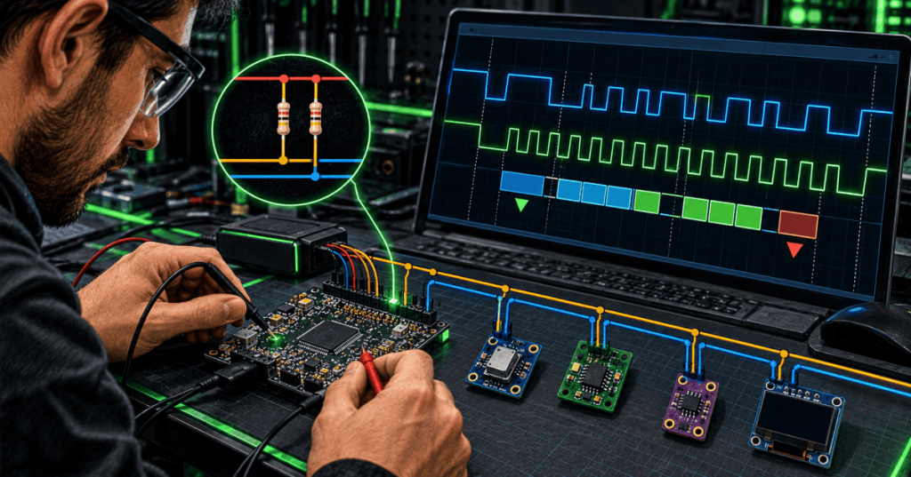
I²C troubleshooting means proving that the two-wire bus is electrically healthy and that devices are exchanging valid clock, address, data, and acknowledge bits. I²C uses two shared lines: SDA for serial data and SCL for serial clock. NXP’s I²C specification defines both lines as bidirectional and normally pulled high, with devices pulling them low when they need to transmit a zero or hold the bus. For a firmware technician, that makes the first troubleshooting question simple: before blaming code, verify that SDA and SCL actually reach valid high and low levels. This lesson builds on BitcoinVersus.Tech’s 2025 Serial Communication explainer and the 2025 Bitaxe Gamma troubleshooting guide, where firmware, displays, sensors, and board-level communication meet in real hardware.
Start With SDA and SCL Voltage Levels
With the board powered and the bus idle, SDA and SCL should normally sit high through pull-up resistors. If either line is permanently low, common causes include a short to ground, a peripheral holding the bus, a misconfigured GPIO, a damaged device, incorrect voltage translation, or firmware that stopped mid-transaction. If both lines remain high forever, the controller may not be attempting any transfers at all. A multimeter can confirm the idle voltage, but an oscilloscope or logic analyzer is better for seeing actual traffic and edge quality. Never assume that “3.3 V present” proves a healthy bus; a line can idle correctly and still have slow edges, noise, or invalid timing during communication.
Pull-Up Resistors Control Rise Time
I²C devices generally use open-drain or open-collector outputs, so the bus needs pull-up resistors to return SDA and SCL high. Pull-ups that are too weak can make the rising edges too slow, especially with long traces, many devices, connectors, or high bus capacitance. Pull-ups that are too strong increase current whenever a device pulls the line low and can exceed sink-current limits. NXP specifies rise-time limits for each I²C speed mode, so resistor choice is an electrical design decision rather than a universal fixed value. In troubleshooting, compare the actual waveform rise time with the device datasheets and the bus speed instead of blindly replacing resistors with “the usual” value.
Address, ACK, and NACK Tell You Where Communication Fails
After a START condition, the controller sends an address and direction bit. A responding target normally acknowledges by pulling SDA low during the acknowledge clock. If the analyzer repeatedly shows NACK immediately after the address, check the target address, power rail, reset state, wiring, level compatibility, and whether the device is actually present. If the address is acknowledged but later data bytes are NACKed, the failure is farther into the transaction and may involve an unsupported register, invalid sequence, device busy state, or firmware expectation. This is why protocol decoding is more useful than only looking for square waves: the technician can see exactly which byte stopped the conversation.
Use a Logic Analyzer to Separate Hardware From Firmware
Connect the analyzer ground to the board ground, probe SDA and SCL, set thresholds appropriate for the bus voltage, then enable I²C decoding. A useful capture should show START, address, read/write direction, ACK/NACK, data bytes, and STOP. If firmware claims it wrote to a sensor but no transaction appears on the analyzer, look upstream at initialization, pin muxing, clock enables, task execution, or the driver call itself. If valid traffic leaves the controller but the target never acknowledges, move downstream toward power, address straps, reset pins, wiring, pull-ups, and the target device. This same layered method complements OSFTC.002 UART and boot-log troubleshooting: first prove what the firmware says it is doing, then prove what the pins actually do.
A Focused Troubleshooting Order
- Confirm controller and target power rails.
- Confirm a common ground.
- Measure idle SDA and SCL voltage.
- Verify pull-up resistors exist and connect to the correct logic rail.
- Capture SDA and SCL with a logic analyzer or oscilloscope.
- Confirm the controller generates START and clock pulses.
- Decode the address and read/write bit.
- Check whether the target ACKs the address.
- If address ACK succeeds, inspect ACK/NACK on later data bytes.
- Compare the transaction against the target datasheet and expected register sequence.
- If the bus locks low, isolate targets one at a time and check reset/power sequencing.
- Retest after each change instead of changing hardware and firmware simultaneously.
Common Fault Patterns
- SDA low all the time: short, stuck target, controller pin forced low, failed device, or interrupted transaction.
- SCL low all the time: short, controller configuration fault, or a device holding the clock.
- Both lines high with no traffic: driver not running, wrong pins, disabled peripheral clock, firmware path not reached, or controller held in reset.
- Address NACK: wrong address, target unpowered, address strap mismatch, bad wiring, reset asserted, or voltage incompatibility.
- Data NACK after address ACK: unsupported command/register, target busy, wrong sequence, or firmware/data-format problem.
- Rounded/slow rising edges: excessive capacitance or pull-ups that are too weak for the selected bus speed.
- Intermittent errors: marginal rise time, noise, loose connection, poor grounding, voltage translation, power instability, or timing close to specification limits.
Why This Matters in Firmware Work
Many firmware failures that look like “bad software” are really communication failures between the microcontroller and a sensor, EEPROM, display, temperature monitor, clock chip, or power-management device. Bitcoin mining hardware is a good example: the 2025 Bitaxe Gamma troubleshooting article shows how a missing reading can require checking firmware and hardware together, while the 2025 NerdAxe ESP32-S3 firmware-flashing guide covers the recovery side when firmware itself must be replaced. I²C diagnosis sits between those layers: it proves whether the running firmware can actually communicate with the peripheral it depends on.
Exercises
- Explain why SDA and SCL need pull-up resistors.
- Describe what you would suspect if SDA is permanently low before firmware begins normal operation.
- Explain the difference between an address NACK and a data-byte NACK.
- Capture an I²C transaction and identify START, address, direction, ACK/NACK, one data byte, and STOP.
- Create a troubleshooting plan for a temperature sensor that worked before a firmware update but now returns no reading.
- Explain why a multimeter can confirm idle voltage but cannot replace a logic analyzer for protocol diagnosis.
Knowledge Check + Answers
- What are the two I²C lines? SDA for data and SCL for clock.
- Why do the lines need pull-ups? I²C devices normally pull the shared lines low rather than actively driving them high.
- What does ACK mean? The receiving device pulled SDA low during the acknowledge clock to confirm the byte.
- What does an immediate address NACK usually tell you? The expected target did not acknowledge at that address, so check address, power, reset, wiring, and device presence.
- What tool best shows START, address, ACK/NACK, and data bytes? A logic analyzer or oscilloscope with I²C protocol decoding.
- What should you check when both lines are high but no transactions appear? Firmware execution, pin selection/muxing, peripheral-clock setup, initialization, and whether the controller is attempting the transfer.
Elementary Conclusion
I²C troubleshooting is a single focused workflow: prove the two lines, prove the pull-ups, capture the transaction, decode the address, follow ACK/NACK, and then decide whether the fault is electrical, peripheral, or firmware-side. Do not jump straight to reflashing code when a sensor disappears, and do not replace hardware before checking what the bus actually shows. The waveform is the evidence.
Primary reference: NXP UM10204 — I²C-bus specification and user manual.
Editor’s Note
BitcoinVersus.Tech publishes this lesson for technical education and reference. BitcoinVersus.Tech is not a financial advisor.


Leave a comment