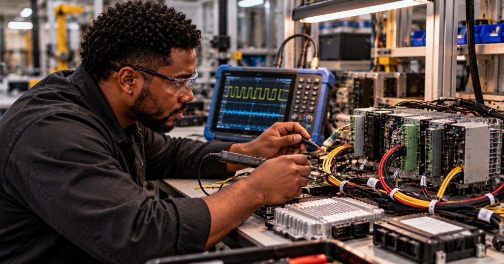
CAN bus troubleshooting begins by separating electrical faults from protocol and firmware faults. A controller may execute correctly yet fail to exchange frames because of missing termination, incorrect bit timing, absent acknowledgment, a failed transceiver, or bus-off recovery.
This is OSFTC.009 in the Open-Source Firmware Technician track, following OSFTC.008: SPI Bus Troubleshooting. The goal is to establish an evidence-based diagnostic procedure for industrial controllers, embedded boards, and networked equipment.
Kvaser: interpreting CAN bus signals on an oscilloscope.
Learning objectives
- Explain CAN_H and CAN_L differential signaling and dominant/recessive bits.
- Measure correct termination on a powered-off bus.
- Recognize ACK errors, error-passive behavior, and bus-off.
- Use an oscilloscope, CAN analyzer, and Linux SocketCAN to isolate faults.
- Document safe corrective action and retest with known-good traffic.
CAN is a shared broadcast bus
Classical CAN uses message identifiers for arbitration, not destination addresses. A dominant zero overrides a recessive one, allowing multiple controllers to arbitrate without corrupting the highest-priority frame. A controller needs both a CAN peripheral and a suitable physical-layer transceiver; MCU TX/RX pins are not equivalent to the CAN_H/CAN_L cable pair.
Physical layer: differential voltage
On a typical high-speed CAN network, recessive CAN_H and CAN_L sit near the same common-mode voltage; during a dominant bit, CAN_H rises and CAN_L falls. Approximate nominal values often cited are 2.5 V/2.5 V recessive and 3.5 V/1.5 V dominant, but actual levels depend on transceiver, loading, and operating conditions. Measure both lines and their difference rather than declaring a fault from a single trace.
Termination and resistance
A conventional linear high-speed CAN trunk has a 120 Ω termination at each physical end. With equipment powered down and no alternate parallel loading, measuring across CAN_H and CAN_L commonly gives approximately 60 Ω because the two resistors are in parallel. About 120 Ω suggests one termination is absent; around 40 Ω can suggest three parallel 120 Ω terminations. These are clues, not universal pass/fail values: inspect actual network topology, internal resistors, isolation, and measurement points.
Never perform resistance measurements on a powered circuit. Confirm the circuit is isolated and follow site safety procedures before attaching test equipment.
Embedded developers discuss why termination belongs at the two physical ends, rather than on every device.
Bit rate and sample point
All classical CAN participants on the same segment must agree on nominal bit timing closely enough to sample frames. Check the configured bitrate, oscillator accuracy, propagation segments, synchronization jump width, and sample point. A 500 kbit/s network has a nominal bit time of 2 µs; 250 kbit/s has 4 µs. CAN FD may use a separate faster data-phase rate, so capture both nominal and data-phase configuration before testing.
Acknowledgment is not application acceptance
A transmitting CAN node expects another active receiver to assert the ACK slot after a valid frame. One isolated transmitter on a perfectly wired bus can repeatedly report ACK errors simply because no other node acknowledges it. An ACK proves at least one receiver accepted the frame at the CAN protocol level; it does not prove an application processed the payload.
Error counters and bus-off
CAN controllers track transmit and receive errors. Repeated errors can move a node from error-active to error-passive and eventually bus-off, at which point the controller stops participating in normal traffic until the configured recovery mechanism runs. A bus-off report is an outcome, not a root cause. Investigate the preceding physical, timing, ACK, or controller faults before forcing repeated restarts.
Use a scope and analyzer together
- First record supply rails, transceiver enable/standby state, ground reference, and wiring continuity.
- With power off, measure termination and check for shorts between CAN_H, CAN_L, supply, and ground.
- With power on, capture both CAN_H and CAN_L with suitable probes and instrument grounding.
- Decode frames at the documented bitrate and record arbitration IDs, CRC/stuff/form errors, ACK state, and timestamps.
- Compare the first failing frame with a known-good node and test a single approved change at a time.
Automotive Diagnosis: CAN_H/CAN_L waveform measurements and shorts-to-ground diagnostics.
Linux SocketCAN examples
On a Linux host with an approved CAN interface, ip -details link show can0 reports interface and state. A controlled lab setup might configure sudo ip link set can0 up type can bitrate 500000 restart-ms 0; use the real approved bitrate and never alter a production bus without authorization. candump -L can0 records timestamped traffic. ip -statistics -details link show can0 helps inspect dropped frames and error counters. cansend can0 123#11223344 transmits a frame and must be restricted to a disconnected test fixture or an expressly authorized network.
Fault isolation examples
- No frames and flat lines: verify power, transceiver standby, connector pinout, termination, and actual transmit attempts.
- Frames visible but ACK errors: confirm a second healthy active node and matching bit timing.
- Repeated stuff/form/CRC errors: inspect ringing, cable stubs, termination, noise, and sample-point mismatch.
- One device triggers bus-off: compare its transceiver voltage, oscillator, firmware timing, and error counters against known-good equipment.
- Scope shows common-mode noise: evaluate the differential signal and actual decoding before concluding communication is broken.
Real troubleshooting discussion: apparent noise on both conductors can be common-mode and may not destroy differential signaling.
Safety and production change control
Never probe an energized vehicle safety network or industrial control bus without authorization, electrical safety controls, and the approved maintenance procedure. Do not attach a new termination, send test frames, or reset a controller on a live critical network simply to see what happens. Isolate a bench harness when possible and preserve configuration and logs before modification.
Technician practice exercise
A four-node CAN segment shows 40 Ω across CAN_H/CAN_L while powered down, and the logger reports intermittent error frames. Two end nodes each contain 120 Ω termination; a middle breakout also has a soldered 120 Ω resistor. Explain why the reading is 40 Ω, which resistor should be disabled, how to verify the physical trunk ends, and what waveform and frame-level evidence would prove the repair.
Knowledge check and answers
- Why approximately 60 Ω? Two 120 Ω end terminators in parallel, with power removed and no other significant loading.
- Can a lone CAN transmitter produce ACK errors? Yes, if no other active receiver acknowledges its valid frame.
- What is bus-off? A CAN controller error-confinement state that prevents normal participation until recovery.
- Does a valid ACK prove the application accepted data? No, it only indicates protocol-level acknowledgment by at least one receiver.
- Why inspect CAN_H and CAN_L together? The receiver responds primarily to differential signaling; common-mode disturbances can appear on both conductors.
Primary references and related lessons
Technical references: Kvaser CAN Protocol Tutorial, Kvaser CAN troubleshooting, and Tektronix CAN decoding and troubleshooting. Related lessons: OSFTC.008, OSFTC.007, and OSFTC.006.
BitcoinVersus.Tech Editor’s Note:
We volunteer daily to ensure the credibility of the information on this platform is Verifiably True. If you would like to support to help further secure the integrity of our research initiatives, please donate using the QR code provided


Leave a Reply