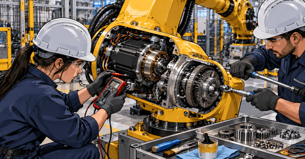
An industrial robot joint is a compact motion system built from a servo motor, feedback device, holding brake, precision reducer, bearings, cables, and controller. When a joint develops heat, noise, drift, backlash, brake faults, or position errors, a technician has to separate electrical, mechanical, and calibration symptoms without creating a second problem. This lesson follows OSRTC.010: Robot Encoder and Backup Battery Service.
Learning Objectives
- Explain how a servo motor, brake, encoder, and reducer work together in a robot joint.
- Distinguish a holding brake from the servo system’s normal controlled stopping function.
- Recognize symptoms associated with motor, brake, bearing, reducer, and cable problems.
- Understand backlash, lost motion, torsional stiffness, vibration, and abnormal heat at a technician level.
- Build a safe inspection sequence before replacing a motor, brake, or reducer.
- Verify a repaired axis without bypassing safety systems or corrupting mastering data.
The Servo Motor Is the Joint’s Torque Source
Industrial robots commonly use closed-loop AC servo motors because the controller must command torque and position precisely while receiving continuous feedback from an encoder or resolver. The servo drive regulates motor current, which produces torque, while the feedback device reports rotor position and speed. In a healthy axis, commanded motion, encoder feedback, motor current, and mechanical movement agree closely. When they do not, the controller may report following errors, overcurrent, encoder faults, or axis-position deviations.
Robot Brakes Are Usually Holding Brakes
Many robot axes use a spring-applied, electrically released brake. When control power is removed, spring force applies the brake so a gravity-loaded axis does not move freely. When the controller enables the axis, the brake coil is energized and the brake releases. The brake is therefore primarily a holding device, not the normal mechanism used to stop a moving robot every cycle. Normal stopping should be performed under controlled servo deceleration whenever the system is healthy.
A dragging brake can create heat, current demand, slow motion, or a burning smell. A brake that does not hold can allow an unsupported axis to drop when servo power is removed. Brake-release testing is therefore a hazardous-energy task. Support the axis, follow the manufacturer procedure, establish the required lockout/tagout state, and never treat a manual brake release as a shortcut around a robot safety system.
Why Robot Joints Need Precision Gear Reduction
A high-speed servo motor usually cannot drive a large robot joint directly. A precision reducer multiplies torque and lowers output speed while preserving repeatability. Depending on the robot and joint, the reducer may use strain-wave, cycloidal, planetary, or other precision gearing. The reducer also contributes stiffness and mechanical accuracy. Wear, lubrication problems, bearing damage, impact loads, or loose interfaces can introduce lost motion, vibration, noise, and position error even when the motor and encoder remain electrically healthy.
Backlash, Lost Motion, and Torsional Stiffness
Backlash is angular free play between mechanical elements when direction reverses. Lost motion is the broader difference between commanded reversal and actual output movement, including backlash, elastic deflection, bearing clearance, coupling movement, and structural compliance. Torsional stiffness describes how much a joint twists under torque. A robot can therefore show poor path accuracy or a visible “snap” on reversal even when encoder feedback at the motor shaft looks normal, because the feedback device may not directly measure every mechanical deflection downstream of the motor.
Heat Is a Symptom, Not a Diagnosis
Motor temperature can rise because of high payload, aggressive acceleration, excessive friction, brake drag, poor cooling, bearing damage, incorrect payload data, mechanical binding, or an electrical problem. Gearboxes can also heat because of friction, lubricant degradation, preload problems, contamination, or overload. Compare the suspect axis against manufacturer limits, recent baseline data, current draw, duty cycle, payload, and neighboring joints before deciding that the motor itself has failed.
Common Symptom Patterns
- Axis drops when servo power is removed: treat as a brake, brake-control, mechanical-support, or load-holding problem until proven otherwise.
- Axis runs hot with high current: inspect payload, friction, brake release, reducer condition, bearings, motion profile, and mechanical interference.
- Axis will not move but servo is enabled: check brake release, drive faults, motor power, interlocks, mechanical jam, and command state.
- Grinding or rumbling noise: inspect reducer, bearings, lubrication, couplings, covers, and loose mechanical interfaces.
- Click or jump when reversing direction: evaluate backlash, lost motion, loose couplings, reducer wear, fasteners, and mastering accuracy.
- Position error after motor work: verify encoder connection, mastering/reference data, coupling alignment, brake operation, and correct motor installation.
- Intermittent servo fault during motion: inspect motor cables, encoder cables, dress-pack movement, connectors, grounding, and axis-dependent cable flex.
- Brake-release alarm: check brake supply, wiring, connector condition, control output, coil state, and manufacturer-specific brake monitoring.
Safe First-Line Inspection
- Record the robot model, axis, alarm text, program state, payload, recent maintenance, and exact symptom.
- Capture controller diagnostics, servo-current trends, temperature information, position errors, and event timestamps before resetting faults.
- Determine whether the symptom occurs at one joint angle, one direction, one speed, one payload, or throughout the axis range.
- Inspect external cables, connectors, dress packs, fasteners, covers, visible contamination, and evidence of impact.
- Listen for repeatable mechanical noise only from a safe position and under an approved diagnostic motion procedure.
- Compare the suspect axis with a known-good axis or historical baseline when the robot design permits a meaningful comparison.
- Before opening a joint or releasing a brake, place the robot in the manufacturer-required service condition and control gravity-loaded energy.
- Use only approved torque specifications, lubrication, replacement parts, mastering procedures, and test routines.
- Do not bypass safety interlocks, force brake outputs, or alter servo parameters simply to make an alarm disappear.
Electrical Checks Need the Correct Isolation Boundary
Motor windings, brake coils, encoders, and controller electronics are different circuits and should not be tested as though they were one device. Resistance checks, insulation testing, continuity testing, and connector measurements must follow the robot manufacturer’s procedure and specified isolation points. High-voltage insulation testers can damage feedback electronics if used on the wrong conductors. Disconnect and isolate only where the service documentation requires it, and preserve encoder/mastering data before disturbing feedback components.
Mechanical Replacement Is Only Half the Repair
Replacing a servo motor or reducer can change the relationship between the feedback device and the robot’s physical zero position. Depending on the design, the axis may require mastering, witness-mark alignment, calibration data restoration, or a manufacturer-specific reference procedure after replacement. Mechanical alignment, connector seating, brake operation, torque values, cable routing, lubrication, and interference checks must all be verified before the robot returns to automatic operation.
Post-Repair Verification
- Confirm all covers, connectors, fasteners, grounding, and dress-pack routing are restored.
- Verify the brake holds when required and releases only under the approved servo-enable sequence.
- Jog at reduced speed through a safe range while checking direction, smoothness, noise, and current behavior.
- Confirm mastering or calibration status before trusting Cartesian positions.
- Run the manufacturer-approved witness, mastering, or reference-position check.
- Compare motor current, temperature, vibration, and repeatability with known-good behavior.
- Return to production only after safety functions, tooling, payload data, and automatic paths are validated.
Hands-On Exercise
- Draw a robot joint showing servo motor, encoder, brake, reducer, output bearing, robot link, motor power cable, and feedback cable.
- Label which components are electrical, mechanical, feedback, and safety-related.
- Create a symptom tree for an axis that is hot, noisy, and drawing more current than normal.
- Create a second symptom tree for an axis that drops slightly when servo power is removed.
- Explain why replacing a motor can require mastering even when the new motor is electrically identical.
Knowledge Check
- What is the main job of the servo motor in a robot joint?
- Why is encoder feedback required in a closed-loop robot axis?
- What is the normal purpose of a spring-applied robot brake?
- Why should a holding brake not be treated as the normal cyclic stopping method?
- What does a precision reducer do?
- How are backlash and lost motion different?
- Name four possible causes of abnormal axis heat.
- Why can a robot show mechanical position error even if the motor encoder is working?
- Why is manual brake release hazardous on a gravity-loaded axis?
- What must be verified after a motor or reducer replacement before automatic operation resumes?
Answers
- To convert controlled electrical current into torque that moves the robot axis.
- The controller needs continuous position and speed information so it can correct motion error and regulate the axis.
- To hold the axis when servo power is removed, especially where gravity could move the joint.
- Repeated dynamic stopping can overheat or wear a brake designed primarily to hold a stationary axis; normal stops are controlled by the servo system.
- It reduces motor speed, multiplies torque, and contributes precision and stiffness between the motor and robot link.
- Backlash is mechanical free play during reversal; lost motion includes backlash plus elastic and structural effects that delay output movement.
- Examples include brake drag, excessive payload, aggressive duty cycle, bearing damage, reducer friction, poor cooling, mechanical interference, and electrical faults.
- The encoder can report motor-shaft position while backlash, reducer wear, bearing clearance, or structural compliance occurs downstream.
- Releasing the brake can remove the mechanism holding a heavy axis against gravity, creating sudden stored-energy motion.
- Brake function, electrical connections, cable routing, mechanical torque/alignment, mastering or calibration, safe low-speed motion, repeatability, and all safety functions.
Previous Related Lessons
- OSRTC.010: Robot Encoder and Backup Battery Service
- OSRTC.007: Robot Preventive Maintenance
- OSRTC.006: Robot Alarm and Fault Recovery
Primary References
- Yaskawa America — Servo Basic Concepts: official servo training covering axis components, feedback, directional motion, homing, and actuators.
- Harmonic Drive LLC — Motion and Robotics Videos: manufacturer resources covering strain-wave gearing, servo gear trains, and precision robotic motion.
- Harmonic Drive LLC — Precision Motion Products: technical background on precision reducers and actuators used in robotics and automation.
Rotation next: Robotics Engineer.
BitcoinVersus.Tech Editor’s Note:
We volunteer daily to ensure the credibility of the information on this platform is Verifiably True. If you would like to support to help further secure the integrity of our research initiatives, please donate using the QR code provided

For best QR-code scanning results, please scan this donation code from a desktop or larger screen. Mobile screens may prevent camera recognition.
BitcoinVersus.Tech provides technical education and analysis for informational purposes only.


Leave a Reply