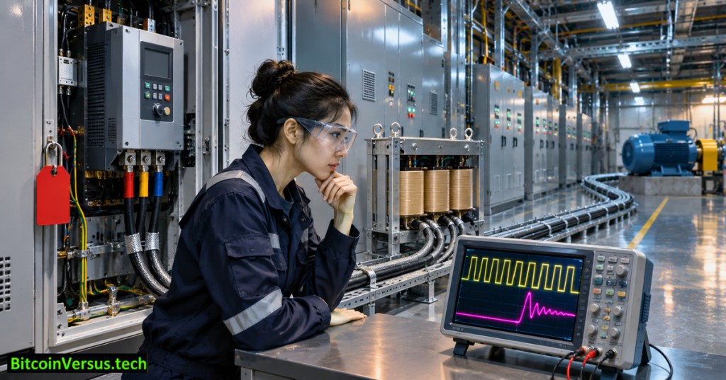
OSEEC.031 explains why the cable connecting a variable-frequency drive (VFD) to a motor can affect winding insulation even when the motor operates at the commanded speed. Modern drives synthesize AC from rapid pulse-width-modulated voltage transitions. A long motor lead behaves partly like a transmission line, allowing portions of a fast voltage wave to reflect at impedance changes. The resulting terminal peak can exceed the voltage step launched by the inverter.
The preceding OSEEC.030 addressed DC-bus overvoltage during braking. Reflected-wave overvoltage is a different phenomenon occurring at the motor end of a PWM cable. OSEEC.018 reviews how the inverter produces its switching waveform.
Why a cable can increase the voltage at a motor
A switching edge travels along the conductor and encounters the motor’s input impedance. When the cable’s surge impedance and the terminating impedance differ, part of the edge reflects. Depending on propagation delay and the edge’s rise time, reflected and incoming voltages can overlap near the motor terminals. ABB’s motor protection guidance describes steep edges, insulation stress and common-mode effects; Rockwell’s application explanation lists cable properties, drive rise time and motor impedance among relevant factors.
Longer cable increases the opportunity for the returning wave to separate from the incoming edge, but there is no universal safe distance. Actual limits depend on drive model, voltage class, switching characteristics, cable design, insulation rating, grounding arrangement and any output filters. An installation outside manufacturer limits requires engineering review, not a guessed extra safety margin.
A numerical example: rise time is not switching frequency
Imagine an illustrative inverter output step changing 600 volts in 0.20 microseconds. Its average edge steepness is 600 V ÷ 0.20 µs = 3,000 V/µs, or 3 kV/µs. The calculation describes the rising edge; it does not establish the motor’s peak reflected voltage. The switching frequency instead counts how many switching events occur per second. Both quantities can matter, but they are not interchangeable.
In a simplified ideal model, a strongly positive reflection can cause the instantaneous motor-terminal voltage change to approach twice the incident step. Real motors, cable loss, termination impedance and repeated edges complicate that approximation. ABB warns that certain applications can produce terminal stresses well above the motor’s nominal voltage; a calculated pulse is not a substitute for a qualified insulation assessment.
Output reactor, dV/dt filter or sine-wave filter?
An output reactor adds impedance and can moderate some switching effects, but cannot guarantee sufficient insulation protection for every long cable. A dV/dt filter is designed to reduce voltage-edge steepness and reflected-wave stress under specified conditions. A sine-wave filter attenuates PWM components more extensively so the motor sees a smoother waveform. All options require compatible ratings, placement, thermal management and approval from the drive and filter manufacturers.
Do not confuse motor-side filtering with an input harmonic or electromagnetic-interference filter. They solve different problems. Common-mode bearing currents may also require dedicated mitigation. ABB’s bearing-current guidance cautions against assuming one corrective measure works for every installation.
Read-only field assessment
Record the drive model and voltage class, motor nameplate and inverter-duty rating, actual installed lead length, cable type, shield termination, and presence of a manufacturer-approved output filter. Compare the complete configuration against the drive manual and motor insulation requirements. Document prior motor failures, abnormal cable heating and maintenance history. OSEEC.017 explains drive selection, while OSEEC.029 distinguishes Safe Torque Off from electrical isolation.
Never attach an ordinary grounded oscilloscope probe to an energized VFD output, disconnect motor leads under power or bypass enclosure interlocks. High-energy switching circuits require qualified personnel, approved differential instrumentation and documented isolation procedures. Learning conclusion: motor-lead length is an engineering variable, not a stand-alone filter specification. Evaluate the entire drive–cable–motor system before selecting protection.


Leave a Reply