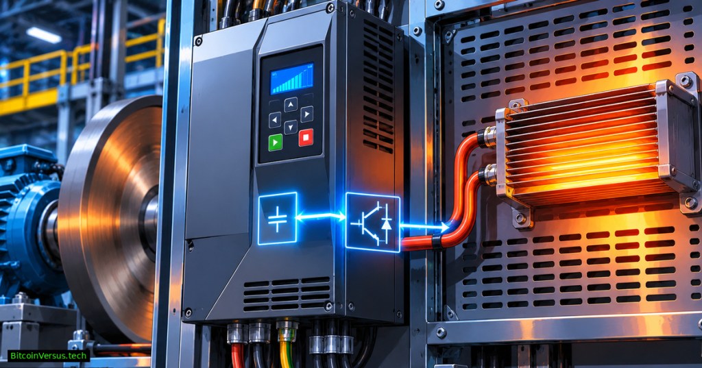
OSEEC.030 explains a common variable-frequency-drive (VFD) fault: an accelerating motor works normally, but the drive trips as soon as a heavy flywheel, conveyor or descending load is told to slow down. The cause may not be a wiring defect. When a motor is driven by its load during deceleration, mechanical energy can return through the inverter into its DC bus, forcing bus voltage upward. Schneider Electric’s braking guidance connects rapid stopping and overhauling loads with braking-resistor applications.
Video: AutomationDirect, “DURApulse GS4 VFD Dynamic Braking” (October 18, 2017). A manufacturer demonstration of dynamic braking on a specified drive family.
Where the energy goes
The rectifier and DC-link capacitors supply the inverter while motoring. During an overhauling or rapidly decelerating condition, power can flow in the opposite direction from the motor toward the DC link. A diode-front-end drive ordinarily cannot return that excess energy to the supply, so DC-link voltage can rise until protective controls intervene. For a foundation in rectification and PWM, review OSEEC.018: VFD Engineering.
A braking chopper is a controlled electronic switch, frequently built around a power semiconductor. Once the DC bus reaches its specified switching threshold, the chopper connects a properly matched resistor so regenerative energy is converted into heat. A resistor alone cannot substitute for a compatible chopper. Schneider Electric explains the separation between switching and heat dissipation; ABB documents the same principle in its ACS880 brake units.
Why faster stops can create faults
A shorter programmed deceleration ramp demands faster removal of kinetic energy. Without enough braking capability, drives may extend the ramp when supported, coast, or report DC-bus overvoltage. The actual response depends on the drive model, configuration, motor and load. Motor power rating alone does not establish resistor size; inertia, braking frequency, duty cycle, permissible resistance, cooling, and thermal protection all matter.
Video: VFD Code, “Sizing a Dynamic Braking Resistor, for Stopping an Inertia Load” (January 30, 2026). An educational calculation demonstration; manufacturer design limits still govern.
Worked example: energy versus heat
Consider a hypothetical deceleration that transfers 5 kW to a resistor for four seconds. The energy is 5,000 W × 4 s = 20,000 joules, or approximately 5.56 watt-hours. If identical stops occur once every 60 seconds, the idealized cycle-average thermal load is 20,000 J ÷ 60 s = 333 W. Both figures are calculated examples, not measured drive values. The resistor must also survive the higher short-duration pulse and any overlapping stops.
A 333 W average does not justify selecting a resistor marked 333 W. The allowable ohmic range and peak duty depend on the specific chopper and manufacturer-approved combinations. Schneider Electric’s resistor-selection guidance emphasizes both braking energy and the load cycle. The worked example deliberately excludes mechanical losses, bus limits, wiring effects and ambient derating.
Dynamic braking is not the same as regeneration
Resistor braking deliberately releases energy as heat. A compatible regenerative drive can instead return usable energy to the supply. ABB describes energy recovery through regenerative supply hardware. Neither approach means the machine is electrically isolated or motion-safe. Compare OSEEC.029 on Safe Torque Off and OSEEC.028 on safety relays.
Video: Jim Pytel / Big Bad Tech, “Motor Drive Deceleration and Braking Methods” (February 25, 2017). An independent lecture distinguishing coast, injection, resistor, and regenerative methods.
A read-only troubleshooting workflow
First, capture the drive fault code, timestamp, model, software revision and deceleration profile from approved operator displays or logs. Next, compare fault occurrence with commanded stops, load direction, speed and operating duty. Check documented brake-chopper availability, resistor specifications, ventilation and thermal-alarm history against the specific manufacturer manual, without changing settings. If shaft behavior also appears abnormal, consult OSETC.044 on alignment and soft foot.
Safety boundary: Never open drive enclosures, touch DC-link terminals, handle braking resistors, bypass interlocks, change stopping ramps or perform live voltage checks based on a web lesson. DC buses can retain hazardous energy after supply power is removed; resistors can remain dangerously hot. Qualified personnel must follow the equipment manual, approved isolation procedures and appropriate verification. Rockwell Automation’s dynamic braking manual warns specifically about live DC-bus potential and misleading indicator LEDs.
Engineering takeaway
An overvoltage trip during deceleration often points to an energy-management mismatch, not simply a defective VFD. Diagnose the load and duty, verify the approved braking architecture, and treat safety isolation as a separate design requirement. OSEEC.017 on motor starting provides useful background on matching motor controls to electrical and mechanical demands.
Editor’s Note: The technical explanation was checked against ABB, Schneider Electric and Rockwell Automation material, with independent educational video listings. The four-second power scenario is hypothetical. No energized equipment, drive configuration, video playback or mobile layout was tested; manufacturer literature and qualified engineering review govern real installations.
We volunteer daily to ensure the credibility of the information on this platform is Verifiably True. If you would like to support to help further secure the integrity of our research initiatives, please scan the QR code below

BitcoinVersus.Tech is volunteer-supported. Confirm the recipient 3C9o19EH5HSiwEPyCTmEKzxhNCbo2X6TTb and amount before any Bitcoin payment. Transfers are generally irreversible.
Disclaimer: Educational information only, not authorization to change industrial motor controls or operate hazardous equipment. Follow site procedures, applicable standards, manufacturer requirements and qualified professional supervision. No financial, investment or certified safety advice is provided.


Leave a Reply