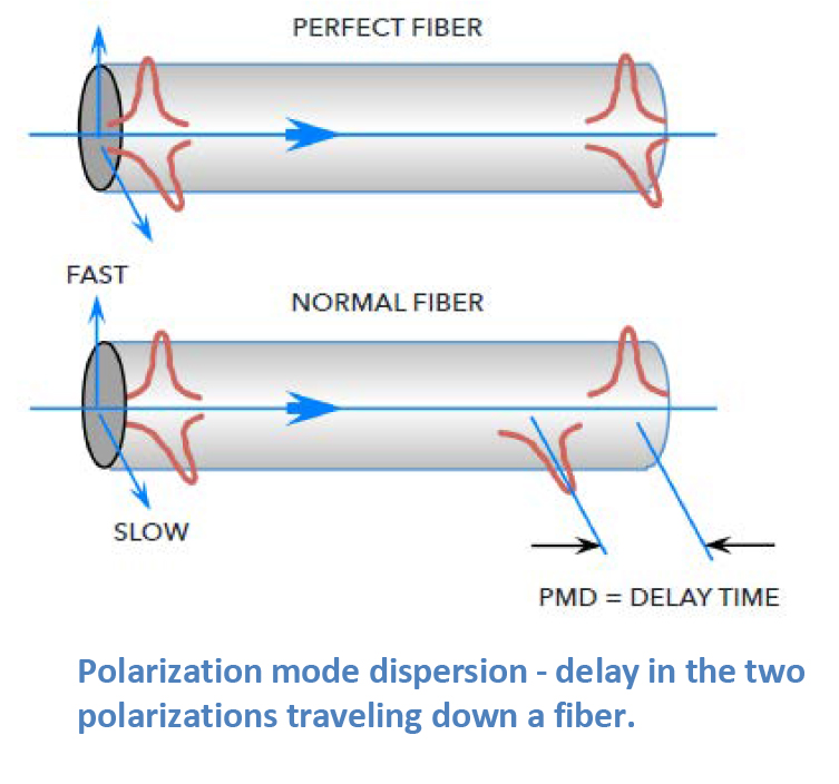
Polarization Mode Dispersion (PMD) refers to the distortion of optical signals caused by slight differences in the propagation speed of light’s polarization modes as they travel through fiber.
In an ideal optical fiber, light of all polarization states should move uniformly.
However, imperfections, asymmetries, and environmental stress within the fiber cause birefringence—splitting the light into two polarization modes that travel at different velocities.
Over long distances, this results in signal spreading, reduced bandwidth, and degraded performance in high-speed communication systems.
PMD is typically measured in picoseconds per square root kilometer (ps/√km) and becomes increasingly significant in long-haul, high-data-rate networks such as 40G, 100G, and 400G systems.
Minimizing PMD requires precise fiber manufacturing, proper cable installation techniques, and active compensation equipment in advanced optical networks.
BitcoinVersus.Tech Editor’s Note:
We volunteer daily to ensure the credibility of the information on this platform is Verifiably True.
If you would like to support to help further secure the integrity of our research initiatives, please donate here: bc1qrved9tfquym6u3age7xhmnkjs2lq8j9aulperagkuhtuk5w5c35ssfpge8
BitcoinVersus.tech is not a financial advisor. This media platform reports on financial subjects purely for informational purposes.


Leave a Reply