Elementary Overview
An industrial robot alarm is evidence that the controller detected a condition it could not safely or correctly continue through. The technician’s job is not to make the red message disappear. The job is to identify the first failed condition, correct the physical or logical cause, then verify that the robot can return to service without recreating the fault.
This lesson follows OSRTC.005: Robot I/O and PLC Handshakes. Earlier lessons established robot safety, teach-pendant operation, mastering and encoder references, and end-effector and TCP setup. Fault recovery combines all of those systems.
Read The Alarm Before Resetting It
The first rule of robot troubleshooting is simple: capture the evidence before pressing reset. Record the alarm code, alarm text, affected axis or device, operating mode, program line, robot position, timestamp, and what the cell was doing when the fault appeared. If several alarms occur together, preserve the order because the earliest alarm is often closer to the root cause while later alarms are consequences.
Use the teach pendant alarm history, event log, or diagnostic screen supported by the controller. A servo-off message after an emergency stop does not automatically mean the servo amplifier failed. A lost-ready handshake after a protective stop may simply be downstream of the original motion fault. Troubleshooting becomes faster when the sequence of events is preserved.
Classify The Fault Before Replacing Parts
Most industrial robot faults can first be sorted into a few broad families: safety and stop-state faults, servo or drive faults, encoder or position-reference faults, overtravel and motion-limit faults, I/O or PLC permissive faults, end-effector or process-device faults, and program or application faults. Classification does not solve the problem, but it tells the technician which subsystem to test first.
For example, a robot that cannot enable servo power after a gate was opened should be investigated through the safety chain and interlocks and permissives before anyone swaps a motor. A robot that enables correctly but one axis immediately reports position-feedback loss points much more directly toward encoder, cabling, servo electronics, or mastering-related evidence.
Safety Stops, Protective Stops, And Hardware Faults Are Different
A technician must distinguish an emergency stop, a safeguard stop, a vendor-specific protective stop, and a hardware or motion fault. Universal Robots, for example, describes a protective stop as a controller response when the robot approaches or exceeds an operational limit; recurring protective stops must be investigated rather than automatically reset. Causes can include incorrect payload or center-of-gravity data, collisions, excessive acceleration, joint limits, singularities, mounting problems, or application forces.
The practical lesson is broader than one manufacturer: a stop state describes what the controller did, not necessarily why it did it. Always identify the triggering condition before restarting automatic operation. Repeatedly acknowledging the same stop without correcting its cause converts a useful diagnostic warning into a recurring production hazard.
Servo Faults Start With The Drive Chain
The robot motion chain is approximately controller → servo command → servo amplifier/drive → motor → mechanical joint → encoder feedback → controller. A fault anywhere in that closed loop can produce a servo alarm. BitcoinVersus.Tech’s robotics drive-systems overview provides the hardware context: the drive converts electrical power into controlled motor torque while feedback closes the position and velocity loop.
A technician should therefore ask whether the alarm points to command, power, amplification, motor current, brake state, feedback, or mechanical loading. An amplifier overtemperature alarm may be caused by blocked cooling. An undervoltage alarm may come from incoming power or a shared DC bus rather than the individual motor. An overcurrent fault may come from a collision, seized joint, damaged motor cable, failed amplifier, or an axis being commanded against a hard mechanical condition.
Shared Power Faults Can Affect More Than One Axis
One useful diagnostic pattern is whether the fault appears on one axis or across several axes at the same time. If multiple servo amplifiers report the same DC-bus or power condition, the source may be upstream in the common supply. If only one amplifier reports the condition while neighboring units remain normal, the fault may be local to that amplifier, its connection, or its feedback path.
This is the same upstream/downstream reasoning used in robot I/O troubleshooting. Do not start at the most expensive component. Start at the first point where the system stops matching the expected state. High-energy electrical measurements must only be performed by qualified personnel using the manufacturer procedure and facility safety rules.
Encoder And Position Faults Require Evidence Before Remastering
An encoder or pulse-coder alarm can mean lost feedback, invalid absolute-position data, a cable problem, backup-power loss, or a mechanical/service event that changed the relationship between the motor and joint. That does not mean the technician should immediately remaster the robot. First confirm the alarm, affected axis, maintenance history, encoder status, connectors, motor work, and whether the physical joint reference is still trustworthy.
OSRTC.003 explains why mastering is a reference relationship between the physical joint and controller position data. Writing new mastering values can hide a mechanical or feedback problem if the original cause is not corrected first.
Overtravel Is A Position Problem Before It Is A Reset Problem
An overtravel fault means an axis reached or exceeded an allowed motion boundary. Depending on the robot, that boundary may involve software limits, hardware limit switches, safety-rated axis limits, or a combination of protections. Before recovery, identify which axis is in fault, which direction caused the limit, and why the robot reached that position.
Possible causes include manual jogging, an incorrect taught point, a shifted user frame, incorrect mastering, an external axis mismatch, or an abnormal program path. Manufacturer-specific overtravel-release procedures may temporarily permit limited recovery motion; those procedures must be followed exactly because ordinary motion protections can be altered during recovery.
A Collision Alarm May Be Mechanical, Programming, Or Payload Related
When a robot reports a collision or torque-related stop, inspect the complete application before assuming a joint is defective. Check whether the payload, center of gravity, TCP, and end effector are correct; confirm that external cables are not snagging; inspect the fixture and part; review speed, acceleration, blending, and the exact programmed motion where the stop occurs.
A collision that happens at the same program point every cycle is different from an intermittent stop across unrelated poses. Repeatable position-specific faults suggest path, fixture, payload, singularity, or application-force problems. Random faults may push the investigation toward wiring, feedback, loose mechanics, power, intermittent sensors, or controller hardware.
I/O Faults Can Look Like Robot Faults
A robot can be mechanically healthy and still sit in FAULT because the workcell never returns a required permissive. If a gripper-closed input, fixture-ready signal, conveyor clear bit, remote enable, or PLC reset handshake never arrives, the robot program may stop even though every servo axis is healthy.
Use the signal-path method from OSRTC.005: physical device → wiring → controller input → logic condition → output → next device. Verify proximity and limit sensors at both the field device and the robot/PLC monitor instead of assuming an illuminated sensor LED means the controller received the signal.
Use The First Failed Dependency Method
A strong recovery process follows dependencies in order. First ask whether safety permits motion. Then ask whether controller and servo power are healthy. Then ask whether encoder and joint-position feedback are valid. Then check whether the program, frames, payload, and motion limits are valid. Finally check external I/O, end effectors, fixtures, and process equipment.
This method prevents parts swapping because every layer depends on the layer before it. A PLC handshake cannot complete if the robot remains in a safety fault. A motion program cannot run correctly if the robot has invalid mastering. A mastering procedure cannot repair a seized gearbox or damaged encoder cable.
A Practical Fault-Recovery Sequence
- Stop and assess personnel, robot, tooling, product, and fixture condition.
- Record the exact alarm code, text, timestamp, axis, operating mode, and program location.
- Review alarm history and identify the earliest meaningful fault.
- Classify the fault as safety, servo/power, encoder/mastering, motion limit, I/O/process, or program/application.
- Check the first dependency in that subsystem before replacing parts.
- Use the manufacturer manual for any vendor-specific reset, overtravel release, brake release, or mastering recovery.
- Apply lockout/tagout and energy isolation before hands-on service where hazardous energy exposure exists.
- After correcting the cause, clear the fault using the approved procedure.
- Verify manual motion at reduced speed if motion recovery is required.
- Dry-run the affected sequence with adequate clearance before restoring full automatic operation.
- Confirm the fault does not recur and document the final cause and repair.
Do Not Normalize Repeated Resets
If operators routinely reset the same robot fault several times per shift, the workcell is telling you something. Repeated protective stops, servo alarms, handshake timeouts, overtravel events, or collision alarms should become maintenance investigations rather than accepted production procedure. Alarm frequency and timing can reveal degrading fans, cables, batteries, brakes, joints, sensors, fixtures, or application settings before a complete failure occurs.
Trend the evidence when the controller supports it. Compare which alarm appears first, which axis is involved, whether the fault happens cold or hot, whether it follows a specific product or program, and whether it correlates with acceleration, payload, or a particular I/O state. Repetition turns an intermittent fault into data.
Technician Pattern Recognition
- Servo will not enable after gate entry: inspect safety chain, E-stops, guard reset, mode, and permissives before drive hardware.
- One axis reports feedback loss: inspect encoder status, cable, connector, motor work, and position-reference history for that axis.
- Several axes report shared power faults: investigate upstream supply or common DC-bus conditions before individual motors.
- Robot stops at exactly the same point: inspect path, frame, payload, fixture, singularity, limits, and application forces.
- Robot position shifted after maintenance: inspect mechanical coupling and mastering evidence before reteaching production points.
- Automatic cycle will not restart but manual motion is healthy: inspect PLC handshake, remote mode, ready/fault/reset signals, and external permissives.
- Same fault returns immediately after reset: stop resetting and correct the unresolved condition.
Exercises
- A robot faults after a gate opens. List the first five checks before considering a servo-drive replacement.
- Explain why the earliest alarm in a fault sequence can be more useful than the last alarm displayed.
- One axis reports encoder data loss after motor maintenance. Describe the evidence you would collect before remastering.
- Three axes report the same undervoltage condition simultaneously. Explain why this points upstream.
- A collision alarm occurs at the same pick point every cycle. List six application checks before replacing a joint.
- Explain how an I/O permissive fault can prevent automatic motion while manual jogging remains normal.
- Create a recovery checklist that includes alarm capture, root-cause correction, reduced-speed verification, and documentation.
Knowledge Check + Answers
- What should happen before an alarm is reset? Capture the alarm code, context, history, and operating condition so the diagnostic evidence is preserved.
- Does a servo-off message always mean a bad servo amplifier? No. Safety stops, E-stops, permissives, power faults, and other conditions can remove servo power.
- Why compare one-axis and multi-axis faults? Multiple simultaneous faults can point toward a shared upstream dependency such as power or communications.
- Should an encoder alarm automatically trigger remastering? No. Verify the feedback path, maintenance history, mechanical coupling, and reference integrity first.
- What does overtravel mean? An axis reached or exceeded an allowed motion boundary and requires cause identification plus the manufacturer-approved recovery procedure.
- Why are repeated protective stops important? They indicate an unresolved application, motion, configuration, mechanical, or safety-related condition that requires investigation.
- What is the first failed dependency method? Trace the system from safety and power through feedback, motion logic, and external I/O until the first expected condition that is not true is found.
Prior Lessons And References
- OSRTC.001 — Industrial Robot Safety
- OSRTC.002 — Teach Pendant Basics
- OSRTC.003 — Robot Mastering and Calibration
- OSRTC.004 — End Effectors and Tool Center Point Setup
- OSRTC.005 — Robot I/O and PLC Handshakes
- Universal Robots — Understanding Protective Stops
- Universal Robots — Stop Recovery
- Robotics: Drive Systems
- OSETC.011 — Lockout/Tagout and Energy Isolation
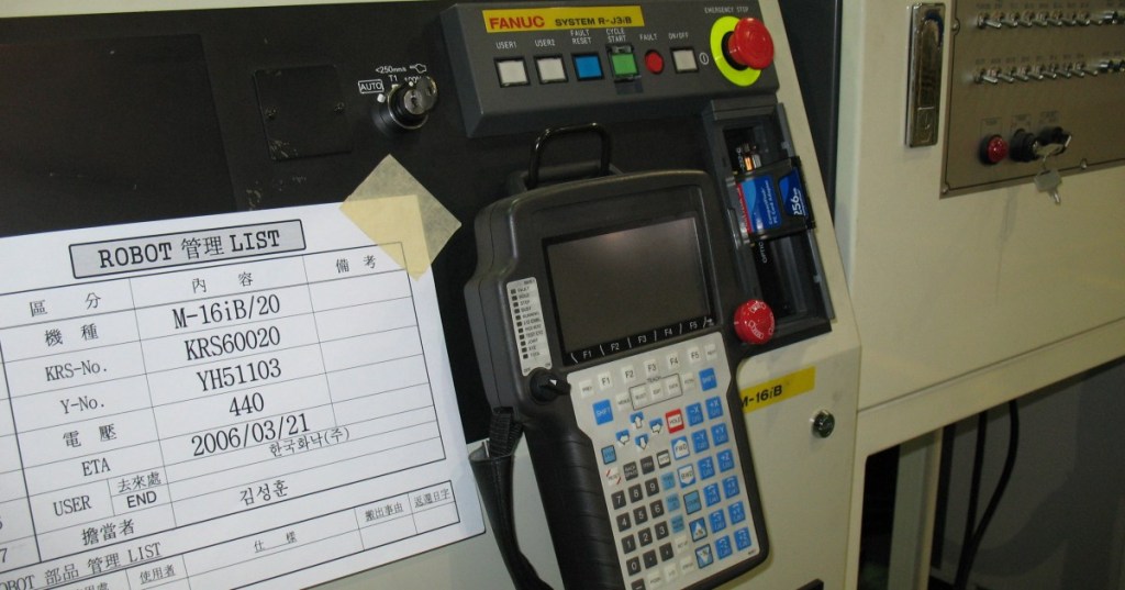
- Featured source photo — Mixabest/Wikimedia Commons, CC BY-SA 3.0; cropped to 1200×630.
Elementary Conclusion
Robot fault recovery is disciplined troubleshooting, not button pressing. Preserve the alarm evidence, classify the subsystem, find the first failed dependency, correct the physical or logical cause, then verify the robot at reduced risk before returning to automatic production. The strongest technicians learn to separate safety faults from servo faults, encoder problems from mastering problems, motion limits from programming errors, and robot faults from missing PLC or process permissives. That is how alarm history becomes a diagnostic tool instead of a reset queue.
BitcoinVersus.Tech
Advertisement
BitcoinVersus.Tech publishes open technical education across robotics, electrical systems, programming, semiconductors, networking, and data centers.
Editor’s Note
Alarm codes, stop categories, overtravel-release methods, brake-release procedures, mastering steps, and energized diagnostic methods are manufacturer- and model-specific. Follow the exact OEM service manual, workcell risk assessment, and facility energy-control procedure. High-energy electrical testing is for qualified personnel only.
We volunteer daily to help keep the information on this platform verifiably accurate. Support our independent research through the support options available on BitcoinVersus.Tech.
BitcoinVersus.tech is not a financial advisor. Content is provided for informational purposes.


Leave a comment