A VLAN trunk is a network link that carries traffic for more than one virtual LAN across the same physical connection. Instead of dedicating a separate cable to every VLAN, managed switches use IEEE 802.1Q tagging so each Ethernet frame can carry VLAN identity as it moves between switches, routers, firewalls, hypervisors, and other VLAN-aware devices. This lesson builds directly on OSNTC.004: VLAN Basics, OSNTC.008: Ethernet Frame Basics, and OSNTC.021: Troubleshooting Switch Ports.
LEARNING OBJECTIVES
By the end of this lesson, explain the difference between an access port and a trunk port, describe where the 802.1Q tag appears in an Ethernet frame, identify the native VLAN, restrict a trunk with an allowed-VLAN list, configure a basic trunk on a Cisco IOS-style switch, and verify whether the intended VLANs are actually forwarding.
THE BASIC IDEA: ONE LINK, MULTIPLE VLANS
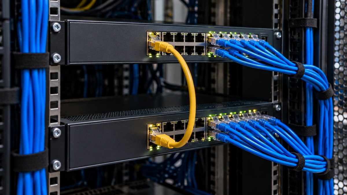
An access port normally belongs to one VLAN and connects an endpoint such as a workstation, printer, server, camera, or network interface card. A trunk port can carry frames belonging to multiple VLANs. Trunks are commonly used between switches and on links to VLAN-aware routers, firewalls, wireless controllers, and virtualization hosts.
CertBros explains VLANs, access ports, trunk ports, 802.1Q tags, and native VLAN behavior.
A Cisco Networking Academy learner highlights networking fundamentals as part of the practical path toward deeper infrastructure and security work.
HOW 802.1Q TAGGING WORKS
IEEE 802.1Q defines VLAN-aware bridging. On a tagged Ethernet frame, a 4-byte 802.1Q field is inserted between the source MAC address and the original EtherType/length field. The tag includes a Tag Protocol Identifier and Tag Control Information. The VLAN Identifier portion is 12 bits, which provides the VLAN numbering space used by modern Ethernet switching. The active IEEE standard family continues to define bridges and VLAN bridges. See the IEEE 802.1Q-2022 standard overview.
When an access-device frame enters a switch, the switch associates it with that access port’s VLAN. If the frame must cross a trunk, the switch can transmit it with an 802.1Q tag that identifies its VLAN. The receiving switch reads the tag, keeps the traffic in the correct logical broadcast domain, and forwards it toward another access port or trunk as appropriate.
ACCESS PORT VS. TRUNK PORT
- Access port: normally carries one data VLAN for an endpoint.
- Trunk port: carries traffic for multiple VLANs over one physical or logical link.
- Tagged frame: includes VLAN identity in the 802.1Q field.
- Untagged frame: has no 802.1Q VLAN tag on the wire.
A trunk is not automatically a faster link. It is a way to multiplex VLAN traffic across one link. If more bandwidth or redundancy is required, a trunk can be carried over a Link Aggregation Control Protocol (LACP) port channel, provided the member interfaces use compatible trunk settings.
THE NATIVE VLAN
On a typical IEEE 802.1Q trunk, one VLAN is designated as the native VLAN. Cisco documentation describes the native VLAN as the VLAN used for untagged traffic received on that trunk, and native-VLAN traffic is normally transmitted untagged. VLAN 1 is the default native VLAN on many Cisco configurations, but it can be changed. Both ends of a trunk should agree on the native VLAN. A mismatch can create confusing forwarding behavior and can interact badly with spanning-tree processing.
The native VLAN should not be confused with the management VLAN or with an access VLAN. These are separate design concepts. A technician should read the actual switch configuration rather than assuming they are identical.
ALLOWED VLANS: CONTROL WHAT CROSSES THE TRUNK
A trunk can be configured with an allowed-VLAN list. If VLAN 10, VLAN 20, and VLAN 30 are the only VLANs that need to cross an uplink, limiting the trunk to those VLANs reduces unnecessary exposure and makes troubleshooting easier. A VLAN may exist on both switches yet still fail across the link if it is missing from the trunk’s allowed list, inactive locally, or blocked by Spanning Tree Protocol.
BASIC CISCO IOS-STYLE CONFIGURATION
The following example configures GigabitEthernet1/0/24 as a static trunk, allows VLANs 10, 20, and 30, and sets VLAN 99 as the native VLAN. Exact syntax varies by platform and software release. Perform configuration work only in a lab or approved maintenance window.
enable
configure terminal
interface gigabitEthernet 1/0/24
 switchport mode trunk
 switchport trunk allowed vlan 10,20,30
 switchport trunk native vlan 99
end
Cisco’s current VLAN configuration guide documents the native-VLAN and allowed-VLAN commands and notes that trunk members in the same EtherChannel must use compatible trunk parameters. See Cisco: Configure VLAN Trunking.
VERIFY BEFORE ASSUMING THE TRUNK WORKS
Verification is more important than the configuration command itself. A trunk can be administratively configured and still fail to carry the expected traffic because of a VLAN mismatch, missing VLAN, native-VLAN mismatch, spanning-tree state, physical-link problem, or inconsistent port-channel configuration.
show interfaces trunk
show interfaces gigabitEthernet 1/0/24 switchport
show vlan brief
show spanning-tree interface gigabitEthernet 1/0/24 detail
show mac address-table interface gigabitEthernet 1/0/24
When reading show interfaces trunk, check the port, encapsulation, trunk status, native VLAN, VLANs allowed on the trunk, VLANs active in the management domain, and VLANs that are actually forwarding. The last category matters because an allowed VLAN is not necessarily forwarding at that moment.
COMMON FAILURE PATTERNS
- Wrong port mode: one side is configured as access while the other is expected to trunk.
- Allowed-VLAN mismatch: the required VLAN is absent from one side’s allowed list.
- Native-VLAN mismatch: each side assigns untagged traffic to a different VLAN.
- Missing VLAN: the VLAN is not created or active on one switch.
- STP blocking: the trunk exists but a redundant path is not forwarding for a VLAN.
- Port-channel inconsistency: LACP members do not share compatible trunk settings.
- Physical fault: cabling, optics, transceivers, or link negotiation fail before VLAN logic is even reached.
Use a layered troubleshooting process. Confirm the physical link first, then switchport mode, VLAN existence, allowed VLANs, native VLAN, spanning-tree state, MAC learning, and finally Layer 3 addressing or routing. This keeps the investigation aligned with the principles in OSNTC.021.
PRACTICAL LAB
In a simulator or isolated lab, create VLAN 10 and VLAN 20 on two switches. Place one endpoint on each switch in VLAN 10 and another endpoint on each switch in VLAN 20. Configure the inter-switch link as a trunk, allow only VLANs 10 and 20, and verify same-VLAN connectivity across the switches. Then remove VLAN 20 from the allowed list and observe the failure. Restore VLAN 20, change the native VLAN consistently on both ends, and verify again.
EXERCISES
- Explain why a trunk does not merge VLAN 10 and VLAN 20 into one broadcast domain.
- Identify the purpose of the 802.1Q VLAN ID field.
- Write a trunk configuration that permits only VLANs 5, 10, and 25.
- Describe what could happen if two trunk endpoints use different native VLANs.
- List at least four verification commands to run before changing a production trunk.
KNOWLEDGE CHECK
1. What is the primary purpose of a VLAN trunk? 2. How large is the 802.1Q tag? 3. What happens to untagged traffic received on a typical 802.1Q trunk? 4. Does an allowed VLAN automatically mean it is forwarding? 5. Why should both ends of the trunk use the same native VLAN?
ANSWER GUIDE
1. To carry traffic for multiple VLANs across one link while preserving VLAN separation. 2. Four bytes. 3. It is associated with the trunk’s native VLAN under the typical configuration described here. 4. No. It can still be inactive or blocked from forwarding. 5. A mismatch can place untagged traffic into different VLANs on each side and produce connectivity, security, or spanning-tree problems.
CONCLUSION AND NEXT STEP
VLAN trunking extends logical Layer 2 networks across shared physical links. The essential technician workflow is to understand the access-versus-trunk distinction, recognize 802.1Q tagging, configure the native and allowed VLANs intentionally, and verify the forwarding state instead of trusting configuration alone. The next Networking Technician lesson should build from this foundation into inter-VLAN communication and Layer 3 switching.


Leave a Reply