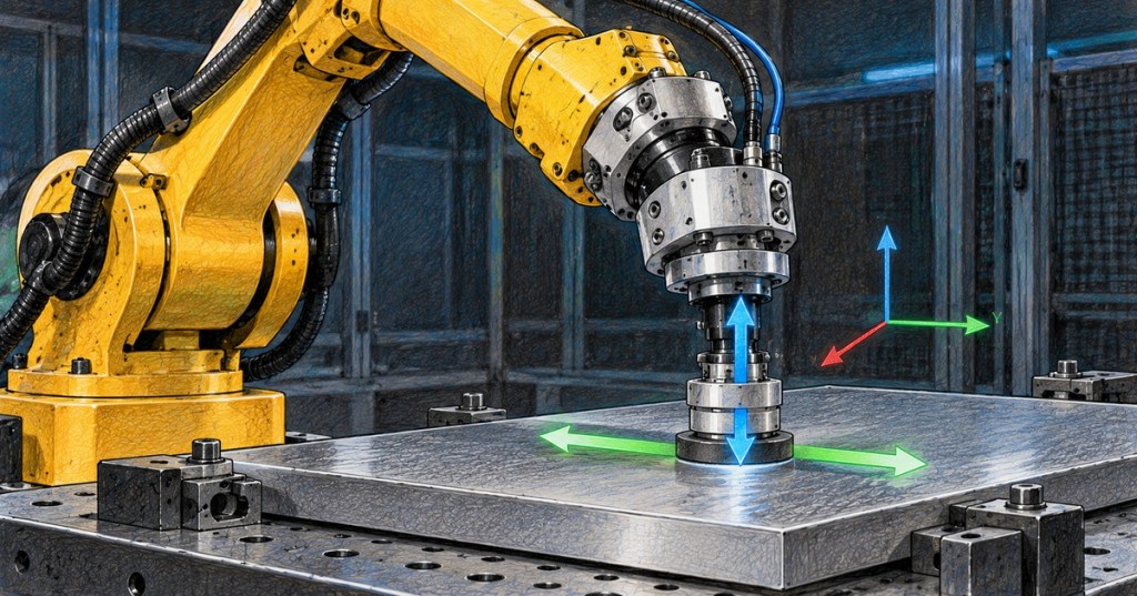
Hybrid motion-force control lets a robot control motion in directions where the end effector is free to move while simultaneously controlling force in directions constrained by the environment. A robot erasing a whiteboard, for example, can command x-y motion along the board while regulating normal force into the surface.
This lesson follows OSREC.008: Impedance and Admittance Control. Impedance control shapes the relationship between motion and force; hybrid motion-force control instead partitions task space so different directions receive different control objectives.
Northwestern Robotics introduces motion control, force control, hybrid motion-force control, and impedance control as distinct robot-control objectives.
Elementary Overview
Imagine pressing a marker against a whiteboard. The marker should move left and right wherever commanded, but it must also push into the board with enough force to keep writing. Motion matters along the board; force matters into the board. Hybrid motion-force control tells the robot which directions belong to each job.
Learning Objectives
- Explain why contact constraints divide task space into motion and force subspaces.
- Express rigid contact as a velocity constraint.
- Relate allowable motion to the null space of the constraint matrix.
- Relate controllable contact force to the complementary constrained wrench space.
- Explain motion and force projection using P and I − P.
- Connect end-effector wrench commands to joint torque using the Jacobian transpose.
- Distinguish hybrid motion-force control from pure force, impedance, and admittance control.
- Identify practical failures caused by incorrect frames, friction, sensor bias, contact loss, saturation, and environment uncertainty.
Rigid Constraints Create Different Control Directions
When a robot end effector contacts a rigid environment, not every Cartesian velocity is physically possible. Modern Robotics expresses idealized end-effector velocity constraints in Pfaffian form as A(θ)Vb = 0, where Vb is the body twist and the rows of A describe constrained motion directions. The allowable end-effector motions lie in the null space of A.
Northwestern Robotics derives constrained robot dynamics and shows how projection methods separate motion-producing torques from forces that act against constraints.
Motion and Force Are Complementary
A rigid constraint removes one or more motion freedoms while creating directions in which the robot can push against the environment. In the ideal frictionless model, a direction blocked by the environment is a natural force-control direction, while a direction left free is a natural motion-control direction. This duality is the foundation of hybrid control.
Modern Robotics explains the duality between force constraints and motion freedoms at rigid-body contacts.
Projection Matrices Separate the Objectives
Let P represent a projection onto the wrench components that create allowable motion. Its complement, I − P, selects wrench components that act against the constraints. A hybrid controller can therefore combine a motion-control wrench and a force-control wrench without asking both controllers to dominate the same task-space direction.
A conceptual command can be written as Fcmd = P Fmotion + (I − P)Fforce. The exact projector depends on the constraint model and dynamics. The important engineering principle is orthogonality of objectives: motion commands are retained only in allowable motion directions, while force commands are retained only in constrained directions.
Northwestern Robotics presents the hybrid motion-force controller and shows how P and I − P project motion and force commands into complementary subspaces.
The Whiteboard Example
Consider an eraser held against a vertical whiteboard. The desired task may control x and y motion across the surface while controlling force along z into the board. Depending on orientation constraints, the controller may also regulate rotational motion about the board normal while controlling moments about axes that the surface constrains. The exact partition depends on the physical contact model.
If the robot tries to position-control the normal direction rigidly while also force-controlling that same direction, the objectives can fight each other. A millimeter of geometric error in the board location can then produce a large force. Hybrid control avoids this conflict by assigning the normal direction to the force objective and the tangential directions to motion.
Engineering Educator Academy gives a second treatment of simultaneous motion control in selected directions and force control in others.
From End-Effector Wrench to Joint Torque
Once the controller computes an end-effector wrench, the robot still needs joint commands. As introduced in OSREC.002: Robot Jacobians, the Jacobian transpose maps an end-effector wrench into joint torque through the familiar relationship τ = JTF, with additional dynamic compensation and limits applied according to the controller architecture.
Modern Robotics reviews Jacobian-transpose-based force control with and without end-effector force/torque feedback.
Selector Matrices in an Aligned Task Frame
In practical applications where the contact directions align cleanly with a chosen task frame, engineers often describe the partition with a selector matrix. A diagonal selector can mark which Cartesian coordinates are motion-controlled, while its complement marks the force-controlled coordinates. This is intuitive for a flat surface but only works correctly when the task frame truly matches the physical constraint directions.
A frame error can therefore become a control error. If the software believes the surface normal points along robot z but the actual surface is tilted, the commanded “normal” force contains unintended tangential components. Always verify the contact frame, TCP, work object, and sensor frame before tuning gains.
Hybrid Control Is Not the Same as Impedance Control
- Pure motion control: tracks position or velocity objectives.
- Pure force control: regulates a desired contact wrench.
- Hybrid motion-force control: assigns different task-space directions to motion and force objectives.
- Impedance control: shapes the dynamic relationship between motion and force.
- Admittance control: converts measured wrench into a commanded motion response through a virtual mechanical model.
These methods can also be combined. A hybrid architecture might use strict force regulation normal to a surface while using an impedance controller tangentially, or use admittance behavior in one subspace and trajectory tracking in another. The labels describe control structure, not mutually exclusive product features.
A robotics discussion illustrates a common engineering question: how force objectives and displacement control are combined in a real manipulator rather than treated as isolated ideas.
Real Contacts Are More Complicated Than Equality Constraints
The clean mathematical model usually begins with rigid, frictionless equality constraints. Real contact is often unilateral: the robot can push into a surface but cannot pull on it unless physically attached. Friction can permit sticking, cause sliding, or change direction with velocity. Contact can also break and re-form. These effects mean that the correct force/motion subspaces can change during the task.
Advanced manipulation therefore uses contact-state estimation, friction-cone reasoning, inequality constraints, complementarity models, or optimization-based control when simple fixed projections are insufficient. Hybrid motion-force control remains the conceptual foundation: determine which freedoms are available and which wrenches the environment can support.
Force Sensor Bias and Frame Errors
A six-axis force/torque sensor reports wrench in its own coordinate frame and also senses tool weight, inertial effects, cable forces, and bias. Gravity compensation requires the tool mass, center of mass, robot orientation, and transforms to be correct. Zeroing the sensor under the wrong load condition can make a correct controller regulate the wrong physical force.
Log the raw sensor wrench, compensated wrench, commanded wrench, task frame, joint torque, pose, and contact state together. If the force vector changes unexpectedly when the robot changes orientation without touching anything, investigate gravity compensation or frame transforms before retuning the force loop.
Contact Transition Is a Control Event
A controller may track free-space motion until contact is detected, then switch to hybrid control. That transition can create force spikes if velocity is too high, detection is delayed, the target surface is misplaced, or integrators contain accumulated error. Contact acquisition should therefore be treated as its own state with conservative approach velocity, bounded force, and explicit transition logic.
Likewise, unexpected contact loss matters. If a force controller continues integrating error after the tool leaves the surface, the robot can accelerate into the environment when contact returns. Anti-windup, contact-state checks, force limits, and state-machine logic are essential practical safeguards.
Stability Depends on the Environment
As with OSREC.008, the environment is part of the closed loop. Rigid surfaces, sensor filtering, time delay, actuator saturation, structural compliance, communication jitter, and aggressive gains can make contact control oscillatory. A controller stable on foam may chatter on steel.
Test with conservative force gains and low approach speeds first. Validate multiple surface stiffnesses and geometry errors. Do not declare the controller stable based only on free-space behavior or one ideal simulation.
Example: Surface Polishing
For polishing a flat workpiece, the robot can trajectory-control tangential x-y motion while force-controlling the surface-normal z direction. The desired normal force maintains tool engagement as small surface-height errors occur. Orientation may be position-controlled or partially force/moment-controlled depending on tool geometry and process requirements.
Useful logs include tangential tracking error, normal force error, end-effector velocity, F/T measurements, joint torque, tool spindle state, surface location estimate, and controller saturation. A finish-quality defect can come from force regulation, path speed, abrasive condition, tool compliance, or geometry—not just one controller gain.
Engineering Workflow
- Define the physical contact and identify constrained versus free motion directions.
- Choose and verify the task frame so its axes match the intended contact geometry.
- Verify robot mastering, TCP, payload, work object, and force/torque sensor calibration.
- Write the constraint model and verify the expected null-space motion.
- Choose the motion and force projectors or selector matrices.
- Test the motion controller without contact.
- Test force regulation at low speed and low force on a compliant test surface.
- Add contact-state logic and conservative transition thresholds.
- Increase force and trajectory bandwidth gradually while monitoring saturation and oscillation.
- Validate against geometry error, different environment stiffnesses, friction changes, and sensor noise.
- Test contact loss and re-contact behavior.
- Archive gains, task frames, sensor calibration, software version, payload, tool, and validation data together.
Engineering Exercise
Model a planar polishing task with free x-y motion and a rigid constraint in z. Define a 6D task vector and create a simple selector representation that assigns x and y to motion control and z to force control. Explain what happens if the actual surface normal is rotated 5° away from the assumed z axis.
Next, assume the desired normal force is 20 N and the measured compensated force is 14 N. Describe the sign and purpose of the force-control correction. Then repeat the reasoning after contact is lost and explain why an unconstrained force integrator could become dangerous.
Knowledge Check
- What does hybrid motion-force control regulate simultaneously?
- What does A(θ)V = 0 represent?
- Where do allowable motions lie relative to the constraint matrix?
- What is the conceptual role of P?
- What is the conceptual role of I − P?
- How is an end-effector wrench mapped into joint torque?
- Why can task-frame error create unwanted tangential force?
- Why is real unilateral contact more complicated than an equality constraint?
- Why should contact acquisition be treated as a separate control state?
- How does hybrid control differ from impedance control?
Answers
- Motion in selected unconstrained directions and force in selected constrained directions.
- A velocity constraint imposed by the environment on the end effector.
- In the null space of the constraint matrix.
- It projects commands into the subspace associated with allowable motion.
- It selects the complementary constrained-force subspace.
- Through the Jacobian transpose, τ = JTF, with the complete controller also respecting dynamics and limits.
- The assumed normal direction no longer matches the physical normal, so projected force contains components along the real surface.
- Real contacts can separate, slide, stick, and obey friction and inequality limits rather than remaining permanently constrained.
- Impact, delay, integrator state, and surface-position error can produce force spikes during the transition from free motion to contact.
- Hybrid control assigns different directions to motion and force objectives; impedance control shapes the dynamic relationship between force and motion.
Elementary Conclusion
Hybrid motion-force control is easiest to remember as move where movement is free; push where movement is blocked. The mathematics identifies those directions, projects each controller into the correct subspace, and combines the results. The engineering challenge is making sure the robot’s model of the contact, coordinate frames, force sensor, and environment matches the real workcell closely enough for that clean mathematical split to remain useful.
Previous Related Lessons
- OSREC.008: Impedance and Admittance Control
- OSREC.007: Robot Force Control
- OSREC.006: Robot Feedback Control
- OSREC.005: Robot Dynamics
- OSREC.002: Robot Jacobians
Primary References
- Modern Robotics — 11.6 Hybrid Motion-Force Control
- Modern Robotics — 8.7 Constrained Dynamics
- Modern Robotics — 11.1 Control System Overview
- Modern Robotics — Chapter 11 Robot Control
BitcoinVersus.Tech Editor’s Note:
We volunteer daily to ensure the credibility of the information on this platform is Verifiably True. If you would like to support to help further secure the integrity of our research initiatives, please donate using the QR code provided

For best QR-code scanning results, please scan this donation code from a desktop or larger screen. Mobile screens may prevent camera recognition.
BitcoinVersus.Tech provides technical education and analysis for informational purposes only.


Leave a Reply