Elementary Overview
A robot can follow a position command perfectly in free space and still fail the moment its tool touches the real world. Contact introduces forces, torques, friction, compliance, uncertainty, and constraints. Force control gives the robot a way to regulate how hard it pushes, pulls, twists, presses, inserts, grinds, or supports instead of commanding position alone.
This lesson follows OSREC.006: Robot Feedback Control. That lesson focused on making measured motion follow desired motion. Here the feedback variable can also be contact force or torque, and the engineering problem becomes the interaction between the robot and its environment.
Motion Control And Force Control Solve Different Problems
In ordinary motion control, the controller tries to reduce position or velocity error. If the desired tool position is xd and the measured position is x, the controller acts on the error xd − x. This is appropriate when the robot is moving through free space and the environment is not imposing a hard geometric constraint.
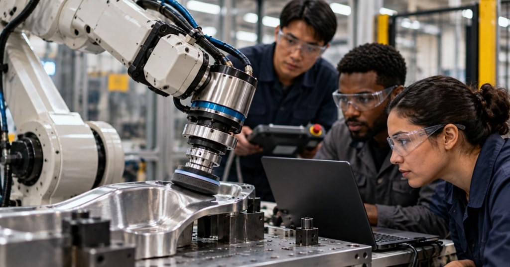
Force control becomes meaningful when contact exists. If a polishing wheel should press against a surface with 40 N of normal force, commanding the tool to a fixed geometric depth is fragile because the surface may be shifted, warped, or dimensionally different. A force controller instead measures contact and adjusts the robot so that the actual force approaches the desired force.
Modern Robotics emphasizes a fundamental constraint: a robot cannot independently impose both motion and force in the same direction. If the robot rigidly imposes motion, the environment determines the resulting contact force. If the robot regulates force, the environment determines how much motion is required to create that force. The control objective must therefore match the mechanics of the task.
Northwestern Robotics — Modern Robotics Chapter 11.5 introduces end-effector force control with and without force/torque feedback.
A Force/Torque Sensor Measures A Wrench
A six-axis force/torque sensor measures three orthogonal forces and three orthogonal moments. The combined quantity is called a wrench:
F = [Fx, Fy, Fz, Mx, My, Mz]T
The sensor may be mounted between the robot wrist and tool, integrated into the robot structure, estimated from joint torque sensors, or inferred from motor current and a dynamic model. Each method has different bandwidth, noise, overload, drift, calibration, and accuracy characteristics.
Sensor readings are meaningful only in a defined coordinate frame. A measured 20 N along sensor z is not automatically 20 N along world z. The wrench must be transformed into the frame used by the controller. The coordinate-frame discipline from OSREC.001 therefore remains essential.
The Jacobian Connects Contact Wrench To Joint Torque
The Jacobian from OSREC.002 connects joint motion to end-effector motion. Its transpose also connects an end-effector wrench to joint torques. Under a quasi-static approximation, where velocity and acceleration terms are small, a useful relationship is:
τ ≈ g(q) + J(q)TFtip
Here τ is the vector of joint torques, g(q) is the gravity-compensation torque, J(q) is the manipulator Jacobian, and Ftip is the desired end-effector wrench. The relation explains why force control is not a separate universe from robot dynamics: a Cartesian contact objective eventually becomes actuator torque through the robot geometry and dynamics.
Near a kinematic singularity, the mapping between joint torques and Cartesian wrench can become poorly conditioned in some directions. A force-control design must therefore respect singularity behavior, actuator limits, joint limits, and the reachable wrench set rather than assuming any desired Cartesian force is physically available.
Closed-Loop Force Control Uses Measured Contact
A simple force loop compares desired wrench Fd with measured wrench Fm. The force error is eF = Fd − Fm. A proportional or proportional-integral term can modify the wrench command or motion command so the error shrinks.
A conceptual PI law is Fcmd = Fd + KpeF + Ki∫eFdt. This is a teaching model, not a universal industrial tuning rule. Real implementations include filtering, saturation, anti-windup, dynamics compensation, sensor bias correction, coordinate transforms, rate limits, safety supervision, and vendor-specific stability constraints.
Force-loop bandwidth cannot be increased without limit. Sensor delay, controller sampling, structural flexibility, gearbox compliance, tool compliance, communication delay, and contact stiffness all affect stability. A controller that is stable against a soft foam surface may oscillate violently against a rigid steel fixture if its gains and filtering are poorly chosen.
Hybrid Motion-Force Control Splits The Task By Direction
Many useful contact tasks require motion control in some Cartesian directions and force control in others. Consider polishing a flat plate. The tool should move along the plate in x and y, while the normal direction z is controlled by contact force. This is hybrid motion-force control.
The same idea appears when writing on a board, opening a constrained door, inserting a part, or sliding an object across a surface. The environment defines directions that are mechanically constrained and directions that remain free. A selection or projection matrix can separate those subspaces so the motion controller acts where motion is permitted and the force controller acts where force should be regulated.
Northwestern Robotics — Modern Robotics Chapter 11.6 explains hybrid motion-force control and the separation of constrained and unconstrained task directions.
Impedance Control Makes The Robot Behave Like A Mechanical System
Direct force control tries to regulate a measured contact force. Impedance control takes a different approach: it specifies how the robot should mechanically respond when the environment pushes on it. A common target behavior resembles a virtual mass-spring-damper system.
One common conceptual form is Fext = Mdẍ + Bdẋ + Kd(x − xd). Sign conventions vary, but the idea is consistent: desired inertia Md, damping Bd, and stiffness Kd define how position changes and external force relate.
A high virtual stiffness makes the robot resist displacement strongly. Lower stiffness makes the robot compliant. Damping removes energy and suppresses oscillation. This is valuable in contact-rich manipulation because a perfectly rigid position command can generate large force when the geometric model is slightly wrong.
MIT’s robotic manipulation notes describe this as making the end effector behave like a chosen mechanical system rather than trying to force exact contact geometry. The controller can move the equilibrium point of the virtual spring while allowing contact forces to determine small deviations around it.
Admittance Control Reverses The Computational Direction
Admittance control measures force and converts that force into a commanded motion. Conceptually, the external force drives a virtual mass-spring-damper model, and the resulting virtual position or velocity becomes the reference for an inner motion controller.
This is useful when a robot has a very strong position-control interface but does not expose direct actuator torque commands. The outer admittance loop says, “Given this measured push, how should the commanded position move?” The inner position loop then tracks that moving reference.
Impedance and admittance can describe similar desired physical behavior, but they are implemented differently. Impedance is often natural on torque-controlled robots. Admittance is often natural on stiff position-controlled robots with external force sensing. The correct choice depends on the available low-level interface, sensor quality, environment stiffness, and required interaction bandwidth.
Force Control Needs Calibration And Gravity Compensation
A wrist force/torque sensor does not measure only contact. It may also see tool weight, cable forces, inertial effects, thermal drift, bias, and mounting offsets. Before using force data for control, engineers normally establish a sensor zero, identify tool mass and center of gravity, transform the wrench into the required frame, and compensate for gravity.
ABB’s Integrated Force Control documentation explicitly includes sensor calibration, load identification, gravity compensation, force-control conditions, and process feedback. Those functions matter because a 3 kg tool can create a large static wrench at the wrist even when the tool is not touching the workpiece.
Calibration should be verified after tool changes, sensor replacement, mounting changes, crashes, or unexplained force bias. A force controller built on a biased measurement can press too hard even while the displayed control error appears small.
Contact Stability Depends On The Environment Too
The robot controller is only half of the closed-loop contact system. The environment contributes stiffness, damping, friction, geometry, and sometimes its own dynamics. A flexible polishing wheel contacting aluminum behaves very differently from a rigid probe contacting a granite fixture.
Engineers should therefore treat force-control tuning as a coupled robot-environment problem. Important variables include controller sample time, force-sensor filtering, structural resonance, contact stiffness, tool compliance, surface friction, actuator saturation, and delays. Excessive gain can produce chatter, force spikes, or instability. Excessive filtering can add phase delay and make the loop unstable even while the signal looks smoother.
A safe commissioning sequence begins with conservative force limits, low speed, verified sensor sign conventions, and a known compliant test setup. Increase performance only after the controller behaves predictably across the expected range of surfaces and contact conditions.
Industrial Force Control Is Already Used In Real Processes
ABB describes Integrated Force Control for assembly, testing, grinding, polishing, deburring, and deflashing. In these applications, force feedback allows the robot to depart from a perfectly predefined path when the real part differs from the nominal CAD geometry. A machining robot can maintain pressure against a variable casting surface; an assembly robot can search for alignment and reduce jamming risk.
The practical advantage is tolerance to uncertainty. Position-only automation often demands precise fixtures because the path assumes the workpiece is exactly where the model says it is. Force-aware automation can use contact itself as information.
Research systems are pushing the same idea into teleoperation and robot learning. Jason Liu and collaborators open-sourced FACTR, a low-cost force-feedback teleoperation system aimed at contact-rich robot tasks.
Jason Liu — open-source FACTR force-feedback teleoperation hardware and software for contact-rich manipulation.
Force information is also becoming part of learning-based grasp planning. GraspSense is one example of research combining perception with force maps for dexterous manipulation.
Robotics Papers — GraspSense research on physically grounded grasp and grip planning using force maps.
Engineering Workflow For A Contact Task
- Define the contact task and the expected constrained directions.
- Choose which directions require motion control and which require force regulation.
- Define the relevant tool, sensor, contact, and world coordinate frames.
- Select and calibrate the force/torque sensing method.
- Identify tool mass, center of gravity, payload, and gravity-compensation parameters.
- Verify force and torque signs by applying small known loads.
- Define safe force, torque, velocity, position, and rate limits.
- Commission at reduced speed against a compliant test surface.
- Tune the control law while monitoring force error, oscillation, phase delay, and saturation.
- Test changes in part position, surface stiffness, friction, and contact geometry.
- Verify recovery behavior for sensor saturation, lost contact, excessive force, singularity approach, and emergency stop.
- Document final gains, filters, frames, payload data, sensor offsets, software version, and acceptance criteria.
Failure Patterns To Recognize
- Force reading changes when the robot rotates in free space: inspect gravity compensation, tool mass, center of gravity, and sensor frame.
- Contact force oscillates against a rigid surface: investigate force-loop gain, delay, filtering, structural resonance, and contact stiffness.
- Robot pushes in the wrong direction: verify sensor polarity and coordinate-frame transforms before tuning anything else.
- Force error integrates while the actuator is saturated: add or verify anti-windup and reachable-force limits.
- Contact force is correct but path quality is poor: inspect the hybrid motion-force decomposition and whether the tangent directions are being over-constrained.
- Force spikes appear at contact entry: reduce approach speed, improve contact detection, add compliant behavior, and review controller transition logic.
- System is stable on one product but unstable on another: compare environment stiffness, tool compliance, friction, geometry, and payload.
Exercises
- A robot sands a flat panel. Define which Cartesian directions should normally use motion control and which direction should normally use force control.
- A six-axis sensor reports Fz = 30 N in the sensor frame. Explain why that value cannot be used as world-Z force without a frame transform.
- Starting from τ ≈ g(q) + J(q)TFtip, explain the physical role of each term.
- Describe why a controller stable against foam might oscillate against steel.
- Compare impedance and admittance control in terms of input, output, and the type of low-level robot interface each suits.
- Create a commissioning plan for a 50 N polishing task that limits force spikes during first contact.
- Explain why a tool change requires rechecking gravity compensation and force-sensor bias.
Knowledge Check + Answers
- What is a wrench? A six-component vector containing three forces and three moments/torques.
- What mathematical object maps an end-effector wrench into joint torques? The transpose of the manipulator Jacobian, together with the robot dynamics and gravity terms.
- Why can force and motion not be independently controlled in the same constrained direction? Imposing one determines the other through the environment mechanics.
- What is hybrid motion-force control? Motion control in unconstrained task directions combined with force control in constrained directions.
- What does impedance control specify? A desired dynamic relationship between motion and force, often represented as virtual mass, damping, and stiffness.
- What does admittance control do? It converts measured external force into a commanded motion for an inner motion controller.
- Why is gravity compensation required for wrist force sensing? Because the sensor measures tool weight and moments in addition to external contact.
- Why can filtering destabilize a force loop? Filtering adds delay and phase lag, which can reduce stability margin.
Prior Lessons And Primary References
- OSREC.006 — Robot Feedback Control
- OSREC.005 — Robot Dynamics
- OSREC.004 — Robot Trajectory Planning
- OSREC.002 — Robot Jacobians
- OSRTC.007 — Robot Preventive Maintenance
- Modern Robotics — Force Control
- Modern Robotics — Hybrid Motion-Force Control
- MIT Robotic Manipulation — Manipulator Control and Contact
- ABB Robotics — Integrated Force Control
Elementary Conclusion
Robot force control begins where pure trajectory tracking stops. A contact-capable robot must measure or estimate how it interacts with the environment, transform that information into the correct frame, map Cartesian wrench objectives into joint actuation, and remain stable across changing contact conditions. Direct force control regulates wrench, hybrid control separates motion and force directions, impedance defines compliant mechanical behavior, and admittance converts measured force into motion. Together these methods let robots assemble, polish, test, insert, deburr, manipulate, and cooperate with the physical world without assuming perfect geometry.
BitcoinVersus.Tech
Advertisement
BitcoinVersus.Tech publishes open technical education across robotics, electrical systems, programming, semiconductors, networking, data centers, firmware, and industrial technology.
Editor’s Note
Force-control limits, gain values, sampling rates, filters, sensor calibration, payload identification, collision supervision, safety functions, and controller interfaces are robot- and application-specific. Follow the exact OEM manual, workcell risk assessment, and facility safety procedure. Commission contact control at conservative force and speed limits before production use.
We volunteer daily to help keep the information on this platform verifiably accurate. Support our independent research through the support options available on BitcoinVersus.Tech.
BitcoinVersus.tech is not a financial advisor. Content is provided for informational purposes.


Leave a Reply