
OSFEC.015 examines how embedded firmware preserves configuration, calibration, counters, and event records when a power failure interrupts storage operations. Flash memory retains data without power, but an interrupted program or erase can leave a partially written record. A reliable design must retain a recoverable previous state, reject incomplete entries, control flash wear, and expose errors to the application instead of claiming an unsuccessful write succeeded.
The lesson advances from OSFEC.014 on memory protection units, which covered isolation and fault containment during execution. The related OSFTC.015 brownout lesson explains power-related resets. OSFEC.013 hardware-in-the-loop testing introduces controlled fault injection. Here, the central design question is which nonvolatile settings remain correct and retrievable after unexpected reset.
Learning Objectives and Prerequisites
- Define program/erase geometry, endurance, durable state, a logical commit, and recoverability.
- Explain why a checksum alone does not make a flash write atomic.
- Describe how Zephyr NVS orders payload and metadata writes and how its optional CRC affects migration.
- Explain littlefs copy-on-write, metadata pairs, and the scope of its documented guarantees.
- Calculate flash-wear sensitivity to write frequency using a published illustrative model.
- Run a host-side interruption-and-corruption simulation with clear hardware limitations.
- Prepare a board-specific power-loss testing and recovery plan using qualified procedures.
Prerequisites: MCU memory maps, reset causes, raw-flash constraints, CRC basics, and software error handling. The executable laboratory example uses Python 3.8+ on an ordinary computer, so no physical flash device is required. Consult the chip datasheet, flash-driver specification, and system’s functional-safety documentation before applying any design to production hardware.
Flash Writes Have Physical Constraints
Many NOR flash devices erase regions to logical ones, then program supported bits toward zero. Erasing again is necessary to restore ones, commonly at a coarser page or sector granularity than a program operation. The precise geometry, alignment, voltage requirements, and erase-cycle rating depend on the device. A CPU memory store and a durable flash transaction are not synonymous. Power can fail before a write, during payload programming, between data and commit metadata, or during garbage collection.
A CRC detects many accidental changes but does not create redundancy or an indivisible update. Two copies are not necessarily independent if erasing a shared physical sector destroys both. A safe design must reason about actual erase blocks, program-unit atomicity, storage layout, and the recoverability of earlier data. The open-source littlefs design guide identifies power-loss resilience, wear leveling, and bounded RAM usage as central embedded-storage requirements.
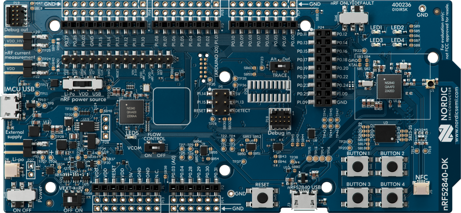
Zephyr NVS: Preserve the Last Complete Entry
Zephyr Non-Volatile Storage (NVS) stores numeric-ID and data pairs across circular flash sectors. Its update sequence writes data first and metadata afterward. Startup ignores entries with missing or invalid metadata rather than treating an interrupted payload as successfully saved. Metadata contains a CRC for the metadata itself; that CRC establishes metadata completeness and does not validate all the payload bytes.
Zephyr offers CONFIG_NVS_DATA_CRC for optional CRC-32 protection of stored data. Enabling the data-CRC option on a previously populated store without CRCs can invalidate existing records, so deployment requires an explicit migration plan. The data CRC is verified for full-data reads rather than every partial read. Applications must check storage return codes and avoid silently treating a failed commit as success.
The NVS implementation needs at least two sectors and maintains a sector for copying live values during reclamation. Sector size follows erase geometry and implementation restrictions. NVS can avoid rewriting a value when the ID and data have not changed, reducing unnecessary wear. Its out-of-space protection avoids certain repeated-erase loops, but insufficient free space must still be handled as an operational failure. The official Zephyr NVS example shows a reboot-persistent counter; the exact board target and sample output can change by release.
Nordic Semiconductor, “nRF Connect SDK hands-on, part 4: Storing data on non-volatile memory” (October 24, 2024). Official free educational tutorial covering persistent data on internal and external storage.
When to Choose littlefs Instead
littlefs provides a file and directory interface rather than only a small numeric-ID key/value store. Its design uses redundant checksummed metadata pairs and copy-on-write structures. New state can be prepared while previously committed structures remain recoverable, reducing the impact of interruption during a supported transaction. The design intentionally bounds RAM consumption and distributes erase activity.
Guarantees apply only when an appropriate block-device driver correctly implements read, program, erase, and synchronization. Code must observe the documented file close/sync and transaction scope; independent application changes across multiple files are not automatically one global atomic operation. Nordic’s storage guide describes settings backends such as NVS, ZMS, and a file-system backend. Select the backend based on application data, flash geometry, and deployed-board support.
CRC-32 is an integrity check for accidental damage, not authentication against an attacker. Secure counters, credentials, or calibration settings may need authenticated storage, access restrictions, and anti-rollback policies. For a separate treatment of firmware signature checks, see OSFTC.013 image integrity.
A Reproducible Host-Side Fault-Injection Lab
The following Python 3.8+ program is a logical two-slot storage simulator. A record contains a four-byte sequence, four-byte value, CRC-32 and a final commit marker. Recovery selects the highest-sequence record with a valid CRC and commit marker. One test interrupts a new write before the commit marker is set, one finishes the write, and one corrupts a previously stored payload. All assertions were executed before preparing the lesson.
Safety and fidelity limitations: Python bytearrays are not NOR flash. The program assumes independently erasable slots and an indivisible final marker update; real silicon may require much larger erase blocks, different program alignment, may tear a marker write, or may share erases across records. Sequence wraparound and simultaneous corruption are also omitted. The code illustrates a recovery policy, not production firmware or a proven physically atomic storage implementation.
"""Host-only teaching model of two independent transactional record slots.
NOT a NOR flash driver, filesystem, or proof of hardware power-loss safety.
"""
import struct
import zlib

RECORD_SIZE = 13
COMMIT = 0xA5

def encode(sequence: int, value: int) -> bytes:
    data = struct.pack('<II', sequence, value)
    checksum = zlib.crc32(data) & 0xffffffff
    return data + struct.pack('<I', checksum)

def decode(slot: bytearray):
    if len(slot) < RECORD_SIZE or slot[12] != COMMIT:
        return None
    data = bytes(slot[:8])
    crc_stored = struct.unpack('<I', bytes(slot[8:12]))[0]
    if (zlib.crc32(data) & 0xffffffff) != crc_stored:
        return None
    return struct.unpack('<II', data)

def recover(slots):
    valid = [entry for slot in slots if (entry := decode(slot)) is not None]
    return max(valid, default=(0, 0), key=lambda entry: entry[0])

def write_record(slots, sequence: int, value: int, power_cut: bool = False):
    inactive = sequence % 2
    # Independently erasable slots are an EXPLICIT SIMULATION assumption.
    slots[inactive] = bytearray([0xff] * RECORD_SIZE)
    slots[inactive][:12] = encode(sequence, value)
    if not power_cut:
        slots[inactive][12] = COMMIT

def main():
    slots = [bytearray([0xff] * RECORD_SIZE) for _ in range(2)]
    write_record(slots, 1, 40)
    assert recover(slots) == (1, 40)
    print('initial recovery:', recover(slots))

    write_record(slots, 2, 99, power_cut=True)
    assert recover(slots) == (1, 40)
    print('interrupted write:', recover(slots))

    write_record(slots, 2, 99)
    assert recover(slots) == (2, 99)
    print('committed write:', recover(slots))

    slots[0][4] ^= 0x01  # Corrupt stored value; CRC invalidates new record.
    assert recover(slots) == (1, 40)
    print('corrupt latest:', recover(slots))

if __name__ == '__main__':
    main()
Save the code as osfec_015_flash_recovery_sim.py and run python3 osfec_015_flash_recovery_sim.py in a host terminal. The test was executed and its assertions passed with the following exact output:
initial recovery: (1, 40)
interrupted write: (1, 40)
committed write: (2, 99)
corrupt latest: (1, 40)
A power cut before the simulated marker preserves sequence 1; a complete later write supplies sequence 2; a flipped data bit makes sequence 2 invalid, so the old intact record remains. An engineer must separately test each physical flash program position, metadata updates, garbage collection, duplicate IDs, and wraparound before claiming reliable recovery on real hardware.
Flash Wear: A Source-Grounded Arithmetic Model
Zephyr documents an illustrative NVS configuration with two 1,024-byte sectors, a four-byte value, eight bytes of metadata per entry, and an assumed erase endurance of 20,000 cycles per sector. The effective logical storage consumption per update is approximately 12 bytes. Using a simple uniform-usage model, the estimated time to reach the assumed number of sector erases varies inversely with write frequency.
Idealized lifetime in minutes ≈ (sector count × sector bytes × nominal erase cycles) ÷ (writes per minute × stored bytes per request). At one saved value per minute: 2 × 1,024 × 20,000 ÷ 12 = 3,413,333 minutes; divided by 525,600 minutes per 365-day year ≈ 6.49 years. Saving every two, five or ten minutes produces about 12.99, 32.47 and 64.94 years in the same arithmetic model.
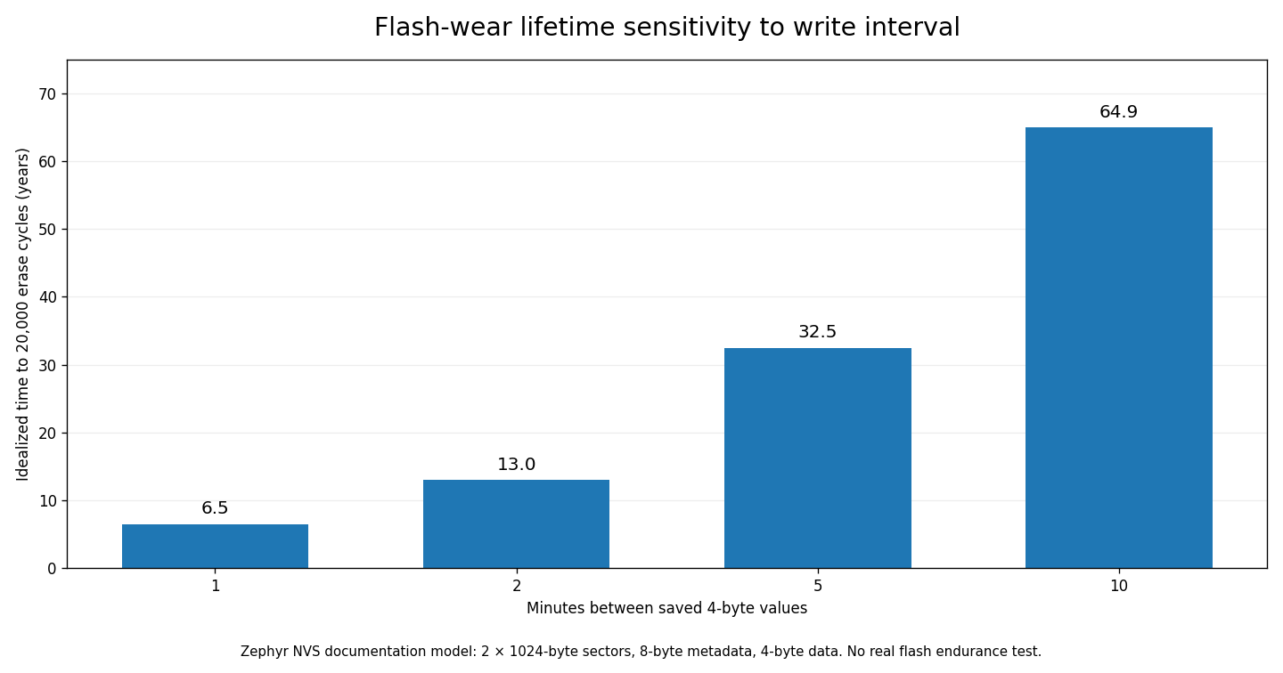
Those numbers are not warranted operating lifetimes. Real flash endurance depends on memory technology, sector cycling, write amplification, storage fullness, bad blocks, voltage, temperature, reclamation, system logging, and actual update distribution. A ten-minute model yielding decades is a warning against overinterpreting a simplified formula. Only the flash maker’s endurance specification and workload qualification can support a real lifetime estimate.
Integrity, Atomicity, Durability and Security
- Integrity: an accidental corruption detector such as CRC-32 helps reject altered payloads; it is not cryptographic authentication.
- Atomicity: an update becomes visible as a complete logical state, or an earlier committed state is used after interruption, within the API’s documented transaction boundary.
- Durability: completed updates survive a specified class of resets and physical failure conditions according to the driver’s documented guarantee.
- Consistency: recovered state obeys application invariants, including schema version, valid ranges, associated calibration identifiers, and dependent settings.
- Authenticity/confidentiality: hostile modification, secret exposure, rollback, and key compromise require controls beyond a CRC.
The older OSFTC.013 integrity lesson explains authenticated firmware images, while OSFTC.014 MCUboot upgrade recovery deals with image-selection state. Neither automatically provides application settings migration or a safe key/value transaction. Those requirements need their own data contract.
Nordic Semiconductor, “nRF Connect SDK hands-on, part 1: Rapid prototyping with nRF Connect SDK” (October 24, 2024). Official free introductory course video establishing the same development environment used by the series’ storage lesson.
Engineering Fault-Injection Acceptance Plan
- Inventory MCU, memory type, storage partition, erase geometry, write-block size, supply limits, SDK/RTOS release, and data-format revision.
- Choose a known-good test configuration and verify the prior record is recoverable before introducing failures.
- Using an authorized bench and qualified personnel, test power interruptions before write, during payload programming, during metadata/commit programming, during garbage collection, and after API completion.
- For every restart, check mount/recovery result, complete data checksum, record version, application bounds, error logging, and whether the old state remains valid.
- Repeat at boundary conditions such as nearly full storage, minimal free sectors, repeated writes, schema changes, lower supply voltage, and prescribed temperature range.
- Record scope precisely: a host simulation does not qualify hardware; a passing single power-cut test does not establish statistical reliability; a failed update must not be reported as successful.
- Add supported tests to version-controlled CI and hardware-in-the-loop coverage. Never repeatedly interrupt production power or bypass protective circuitry for classroom demonstration.
One documented Zephyr issue describes an edge case around a partial final allocation-table entry at a sector boundary. Its existence is not evidence that every current Zephyr release fails in the same way; it is a useful reminder to verify the actual release, reproduction conditions, patch state, and boundary cases for an embedded product.
Troubleshooting Practical Examples
- Settings disappear after reboot: confirm that the storage API reported success, the partition is correct, and the application committed or synchronized data at the required boundary.
- Mount fails after power interruption: preserve the flash image when permitted, identify the exact software version and layout, and inspect source-defined recovery and sector transitions before attempting an erase.
- Unexpected high write rate: compare intended cadence with observed writes, unchanged-value suppression, logging, and application retry loops.
- Data appears valid but belongs to the wrong hardware: verify serialization and schema IDs, per-device calibration version, serialization endianness, and authentication where required.
- CRC errors after enabling a new option: investigate documented data-format compatibility and migration before treating all installed units as physically defective.
- MPU fault while writing internal flash: check the flash driver’s MPU permissions and platform configuration. Zephyr documents a special internal-flash MPU consideration in its NVS troubleshooting guidance.
Documentation-Only Practical Exercises
- Run the complete Python simulation and verify all four printed lines, then record the Python interpreter version and script SHA-256 for reproducibility.
- Add a simulated interruption after the first four payload bytes. Verify that incomplete data never passes the commit and CRC checks.
- Modify the recovery logic to support three logical slots and describe how physical erase geometry changes the design.
- Make the sequence counter wrap and investigate why ordinary numeric maximum is insufficient near wraparound.
- Recalculate the chart for five-minute writes and explain why the apparent 32.47 years must not be advertised as product lifespan.
- Write a test matrix for Zephyr NVS and littlefs on a specific supported board, including sector fullness, sync/close behavior, and migration failures.
Knowledge Check with Answers
- Why can a normal memory write not simply stand in for a durable flash commit? Flash program and erase operations have special physical geometry and can be interrupted.
- What does NVS write before its metadata? Item data; a missing or invalid metadata entry is ignored on initialization.
- Does standard NVS metadata CRC also verify stored user payloads? No; optional data CRC is separately configured and checked.
- What is littlefs built to provide? A constrained, wear-aware and power-loss-resilient file-system model based on copy-on-write and checksummed metadata.
- What did the four-line simulation establish? That its prescribed logical parser selected recoverable records for four host-only scenarios, not that the flash hardware is safe.
- How many bytes does the illustrative Zephyr four-byte value consume per NVS entry? Twelve bytes: four data bytes and eight metadata bytes.
- Why should the 6.49-year estimate not be a maintenance interval? It is a simplified calculation that omits the real device’s wear, error and environment profile.
- Does CRC prevent malicious configuration alteration? No; add appropriate authentication and access controls.
Primary Open Educational References
Zephyr Project NVS technical documentation; Zephyr NVS sample application; Nordic Semiconductor data-storage guide; littlefs open-source project; littlefs design reference; and Nordic nRF52840 DK product documentation. The in-story videos are official Nordic Semiconductor educational lessons.
Conclusion
Crash-consistent firmware depends on storage design from the flash controller through the application contract. Zephyr NVS and littlefs offer proven patterns for incomplete-write detection and recovery, but validation remains specific to the actual device, software version, block driver, state schema and failure conditions. Source-grounded calculations and host demonstrations are learning tools, not substitutes for physical qualification.
Editor’s Note: OSFEC.015 follows the published OSFEC.014 Firmware Engineer lesson and was screened against WordPress and the GitHub curriculum for duplicates. The Python example was executed with all assertions passing; it is explicitly not a real flash or board test. The endurance chart is based on Zephyr’s simplified example, not site telemetry or a manufacturer durability promise. The 1200 × 630 featured cover is an original AI-generated editorial illustration featuring a middle-aged male engineer, visibly different from the prior young woman technician cover. The nRF52840 DK image is an authentic Nordic manufacturer photograph. Both Nordic instructional videos are source-verified; actual playback and screenshot visual inspection are separate QA gates. No custom conceptual schematics are used.

To donate 5,000 sats, scan the QR from another screen with a compatible Bitcoin wallet or use a supported saved-image scanner. Confirm the recipient and amount before sending.
We volunteer daily to ensure the information on this platform is Verifiably True. If you would like to support the research, please scan the QR code.
Educational content is not a substitute for qualified hardware, safety and security engineering or device-specific validation.


Leave a Reply